plants
Adobe Rammed Earth
Build with adobe and rammed earth: soil testing, mixing and curing adobe bricks, rammed-earth forms and compaction, and durable earthen walls.
title: "Adobe and Rammed Earth Construction" subtitle: "Soil as Structure — A Complete Building Manual from Field Test to Finished Wall" author: "Nored Farms" date: "2026"
Content Extraction Summary
Hook Options
1. A 24-inch adobe wall stores enough thermal energy to delay the outside temperature swing by 10–12 hours — so the day's heat arrives inside at midnight and the night's cold arrives at noon. No mechanical system does this. The wall itself is the climate control. 2. The oldest continuously inhabited structures on Earth are not wood, not stone, not steel. They are mud. Taos Pueblo has been occupied for over 1,000 years. Sections of the Great Wall of China are rammed earth that have stood for 2,000. The material is dirt, water, and time. 3. Modern building code evaluates walls by R-value — resistance to heat flow. Adobe has a terrible R-value (R-0.2 per inch). It also outperforms R-19 stick-frame walls in any climate with a diurnal temperature swing greater than 30 degrees. The metric is wrong, not the material.
Key Mechanism
Thermal mass stores and releases heat on a time delay proportional to wall thickness. A 10-inch adobe wall delays heat transfer by approximately 6 hours. A 24-inch wall delays it by 10–12 hours. In climates where daytime highs exceed nighttime lows by 30°F or more, this creates a flywheel effect: the wall absorbs daytime heat and radiates it inward at night when temperatures drop, then absorbs nighttime coolness and releases it during the following day's heat. The result is interior temperatures that remain within a narrow band (68–78°F) without mechanical heating or cooling, provided the wall mass is adequate and the building is properly oriented.
Misconception to Correct
R-value measures resistance to heat transfer in a steady-state condition — a constant temperature difference across the wall. Real buildings do not experience steady-state conditions. They experience cyclical temperature swings. In arid and semi-arid climates with large diurnal swings, thermal mass walls outperform insulation-only walls despite lower R-values because the temperature wave never fully penetrates the wall before it reverses direction. A 24-inch adobe wall in Tucson or El Paso will maintain comfortable interior temperatures year-round with minimal or no HVAC. A 2x6 stick-frame wall with R-19 fiberglass in the same location requires continuous air conditioning. The R-value metric was developed for steady-state cold climates (Minnesota, not New Mexico) and systematically undervalues mass walls.
Practical Application
A homeowner in USDA zones 7–10 with access to suitable soil (15–30% clay, 50–70% sand) can build load-bearing adobe or rammed earth walls for $1–4 per square foot in materials — compared to $8–15 for conventional framing. The labor is intensive but requires no specialized skills beyond soil testing and form construction. In New Mexico, earthen construction has its own building code (NMAC 14.7.4) that can serve as a model for permit applications in other jurisdictions. IRC Appendix S provides a national framework.
Citation-Ready Claims
- Adobe thermal lag: 10-inch wall = ~6 hours, 24-inch wall = 10–12 hours delay (Balcomb, 1992, *Passive Solar Buildings*, MIT Press)
- Taos Pueblo continuously occupied since approximately 1000 CE (UNESCO World Heritage nomination, 1992)
- Rammed earth sections of the Great Wall of China dated to Qin Dynasty, 221–206 BCE (Jaquin et al., 2004, *Construction and Building Materials*, 18(4), 281–286)
- Adobe R-value: approximately R-0.2 per inch for sun-dried earth (Houben & Guillaud, 1994, *Earth Construction: A Comprehensive Guide*, CRATerre-EAG)
- Optimal adobe soil composition: clay 15–30%, sand 50–70%, silt 0–30% (McHenry, 1984, *Adobe and Rammed Earth Buildings*, University of Arizona Press)
- Stabilized adobe minimum compressive strength: 300 psi per ASTM C67 testing (New Mexico Earthen Building Code, NMAC 14.7.4)
- Cement-stabilized rammed earth achieves 600–1000 psi compressive strength (Walker et al., 2005, *Rammed Earth: Design and Construction Guidelines*, BRE Press)
- Lime-stabilized earth increases compressive strength 2–4x over unstabilized earth and improves water resistance (Heathcote, 1995, *Building Research & Information*, 23(2), 101–108)
- Thermal mass effectiveness requires diurnal temperature swing > 15°C (27°F) for passive benefit (Givoni, 1994, *Passive and Low Energy Cooling of Buildings*, Wiley)
- IRC Appendix S adopted 2021 for earthen construction (International Code Council, 2021, *International Residential Code*)
1. Introduction — 10,000 Years of Dirt That Works
One-third of the world's population lives in earthen structures (Houben & Guillaud, 1994). Not because they cannot afford better materials. Because for their climate, soil, and economic conditions, earth is the better material.
Adobe and rammed earth construction have a continuous track record exceeding 10,000 years. The oldest known rammed earth walls — at the Neolithic site of Dadiwan in Gansu Province, China — date to approximately 5000 BCE. Sections of the Great Wall built during the Qin Dynasty (221–206 BCE) used rammed earth, and many of those sections still stand. In the Americas, Taos Pueblo in New Mexico has been continuously occupied since approximately 1000 CE. The Alhambra in Granada, Spain contains rammed earth walls from the 13th century. These are not museum pieces. They are functional structures that have survived centuries of seismic activity, weather, and use.
The modern prejudice against earth construction rests on two errors. First, the assumption that earth buildings are primitive — an aesthetic judgment, not an engineering one. Second, the belief that R-value is the correct metric for evaluating wall performance in all climates. Both are wrong.
Earth walls work through thermal mass, not insulation. They do not resist heat transfer. They absorb it, store it, and release it on a delay. In any climate with a significant difference between daytime and nighttime temperatures — which describes most of the western United States, the Mediterranean, the Middle East, North Africa, Central Asia, and highland Latin America — this delay is the mechanism that maintains comfortable interior temperatures without mechanical systems.
This document covers both adobe (sun-dried mud bricks laid in courses) and rammed earth (moist soil compacted in forms). Both use the same raw material. Both rely on the same thermal mass principle. They differ in construction method, labor profile, and aesthetic outcome. Adobe produces walls with visible coursing and a hand-built character. Rammed earth produces monolithic walls with visible horizontal layers — striated, dense, and modernist in appearance.
The same soil science, foundation requirements, and finishing methods apply to both.
2. Soil Science — Testing What You Stand On
Earth construction succeeds or fails based on soil composition. The wrong soil makes bricks that crack, walls that erode, and floors that turn to dust. The right soil — or the right amendments to marginal soil — produces structures that last centuries.
The Three Components
All soil is a mixture of three particle types, classified by size:
| Component | Particle Size | Role in Earth Construction | |---|---|---| | Clay | < 0.002 mm | Binder — holds the mixture together when dry. Shrinks when drying, swells when wet. | | Silt | 0.002–0.05 mm | Filler — contributes to density but adds no binding strength. Excessive silt weakens walls. | | Sand | 0.05–2.0 mm | Aggregate — provides compressive strength and reduces shrinkage cracking. | | Gravel | > 2.0 mm | Excluded from adobe. Acceptable in rammed earth up to 30% if well-graded. |
Ideal Ratios
The target composition for both adobe and rammed earth:
- **Clay: 15–30%** — Below 15%, the bricks will not hold together. Above 30%, shrinkage cracking becomes severe.
- **Sand: 50–70%** — Sharp sand (angular particles) is far superior to round river sand because angular particles interlock mechanically.
- **Silt: 0–30%** — Tolerable as filler but contributes nothing positive. High-silt soils feel smooth and silky when wet but produce weak, dusty walls.
These ratios are not arbitrary. They represent the balance between binding strength (clay) and dimensional stability (sand). Too much clay and the wall shrinks as it dries, creating cracks that concentrate stress and admit water. Too much sand and the wall has no cohesion — it is a pile of aggregate with nothing holding it together.
Field Tests
You do not need a soils lab. Three field tests, performed in sequence, will tell you whether your soil is buildable or needs amendment.
**Test 1: Jar Test (Sedimentation)**
1. Fill a quart mason jar one-third full of soil. Remove all organic matter and rocks larger than 1/4 inch. 2. Fill the jar with water, leaving 1 inch of air space. 3. Add 1 tablespoon of table salt or 1 teaspoon of liquid dish soap (deflocculant — prevents clay particles from clumping). 4. Shake vigorously for 2 minutes. Set on a level surface. 5. After 1 minute, mark the level of settled material on the jar. This is your sand layer. 6. After 2 hours, mark the new level. The material between the 1-minute mark and the 2-hour mark is silt. 7. After 24–48 hours, mark the final level. The material above the silt line is clay. The water above should be mostly clear. 8. Measure each layer and calculate percentages by volume.
Sand settles fastest because it is heaviest. Silt settles next. Clay stays in suspension longest because the particles carry an electrical charge that keeps them dispersed. If the water is still cloudy after 48 hours, you have a very high clay content.
**Test 2: Ribbon Test (Clay Content)**
1. Take a golf-ball-sized lump of moist soil (should feel like stiff modeling clay — wet enough to be plastic, dry enough to hold shape). 2. Roll it into a cylinder about 1/2 inch in diameter. 3. Flatten the cylinder between your thumb and forefinger, pushing it out over your finger to form a ribbon. 4. Measure the length of the ribbon before it breaks under its own weight.
| Ribbon Length | Approximate Clay Content | Suitability | |---|---|---| | < 1 inch | < 10% | Too little clay. Needs clay amendment or is unsuitable. | | 1–2 inches | 10–20% | Low end of acceptable range. Test bricks before committing. | | 2–3 inches | 20–30% | Ideal range for most earth construction. | | > 3 inches | > 30% | Too much clay. Needs sand amendment to prevent cracking. |
**Test 3: Ball Drop Test (Binding Strength)**
1. Form a tennis-ball-sized sphere of moist soil (same consistency as the ribbon test). 2. Drop it from waist height (approximately 3 feet) onto a hard surface. 3. Observe the result.
| Result | Interpretation | |---|---| | Shatters into many pieces | Too sandy — insufficient clay binder. | | Flattens into a pancake without cracking | Too much clay — will shrink and crack during curing. | | Breaks into 3–5 large pieces with rough edges | Good balance of clay and sand. Proceed with test bricks. | | Holds shape with minor cracking | Slightly clay-heavy but workable. Consider adding 10–15% sand. |
Amendments
Most soil needs adjustment. This is normal, not a problem.
**Adding sand to clay-heavy soil:** Use sharp (angular) sand, not round builder's sand. Add sand in 10% increments by volume, mix thoroughly, and re-run field tests until the ribbon test yields 2–3 inches. For a soil testing at 40% clay, you will typically need to add 30–50% sand by volume of the original soil.
**Adding clay to sandy soil:** If clay content is below 15%, add bentonite clay (available at feed stores as pond sealant) at 5–10% by dry weight, or source clay-heavy subsoil from your property. Dig below the topsoil horizon — clay content increases with depth in most soils.
**Stabilization:** Adding Portland cement (5–10% by dry weight) or hydrated lime (6–12% by dry weight) to the soil mix creates stabilized earth — stronger, more water-resistant, and more dimensionally stable than unstabilized earth.
- **Portland cement** reacts with water to form calcium silicate hydrate crystite bonds that lock soil particles together permanently. Cement-stabilized earth does not soften when wet. It works best with sandy soils (high sand content gives the cement more surface area to bond). Cement works poorly with high-clay soils because the clay interferes with hydration.
- **Hydrated lime** reacts with clay minerals through a pozzolanic reaction, converting soft clay into calcium silicate — a harder, less reactive mineral. Lime works best with clay-heavy soils. It reduces plasticity, increases compressive strength 2–4x (Heathcote, 1995), and dramatically improves water resistance. Lime-stabilized earth is breathable (vapor-permeable), unlike cement-stabilized earth.
**Rule of thumb:** Sandy soils get cement. Clay soils get lime. Soils in the ideal range often need neither.
3. Adobe Brick Making — Form, Mix, Cure
Adobe is the simpler of the two methods. You make bricks. You dry them. You lay them in courses with mortar. The process is ancient, manual, and slow — which is why it produces such consistently good results. Speed is not a virtue in earth construction. Patience is the technology.
Forms
Adobe molds are open-topped rectangular frames — no top, no bottom. Standard brick size in the American Southwest is 4 x 10 x 14 inches (height x width x length), yielding a brick that weighs 30–35 pounds when cured. This size represents a balance: heavy enough for good thermal mass, light enough for one person to lift and place repeatedly.
**Building forms:**
- Material: 3/4-inch plywood or 1-inch dimensional lumber (pine or cedar).
- Inside dimensions: 4 x 10 x 14 inches per cavity.
- Build multi-cavity forms (2–4 bricks per form) to increase production speed.
- Bevel the inside edges slightly — a 5-degree draft angle makes brick release easier.
- Coat the inside surfaces with used motor oil, linseed oil, or diesel fuel before each pour to prevent sticking.
A single person working steadily can produce 40–80 bricks per day with a 2-cavity form. A crew of three with a mechanical mixer and 4-cavity forms can produce 200–400 bricks per day.
Mixing
The mix ratio by volume (not weight) for standard unstabilized adobe:
- **3 parts sand** (sharp/angular preferred)
- **1 part clay-rich soil**
- **Water to consistency** — the mix should slump but not flow. It should hold a handprint when pressed but not stick to your hands. Too wet and bricks slump in the form. Too dry and they do not fill corners and leave voids.
- **Fiber (optional but recommended):** Chopped straw, hay, or dried grass at roughly 1 part fiber per 10 parts soil by volume. Fiber does not add compressive strength. It controls shrinkage cracking during drying by distributing tensile stress across thousands of small fibers rather than concentrating it at a few crack initiation points.
For stabilized adobe, add:
- **Portland cement: 5–8% by dry weight of soil** (for sandy mixes)
- **Hydrated lime: 6–10% by dry weight of soil** (for clay-heavy mixes)
Cement or lime must be mixed dry with the soil before adding water. Once water hits cement, you have approximately 45 minutes of working time before initial set.
**Mixing methods:**
- **By hand:** Dump measured proportions onto a clean surface (concrete slab, plastic tarp). Mix dry ingredients with shovels. Form a crater, add water gradually, fold the perimeter into the center. Continue until uniform color and consistency. This is the slowest method but works for small batches (20–40 bricks per mix).
- **By machine:** A mortar mixer or plaster mixer handles adobe mix well. A concrete mixer works but the mix tends to ball up inside the drum rather than folding properly. Best machine option is a plaster mixer with paddle blades, which shears the clay and incorporates water evenly.
- **By livestock:** The traditional method. Pile the soil in a pit or on a tarp. Add water to make a thick slurry. Walk livestock (horses, cattle, donkeys) through the pit for 30–60 minutes. The hooves knead the clay, break up clods, and incorporate straw if thrown in during the process. This is not primitive nostalgia — it is the most energy-efficient method for large batches and produces an exceptionally well-mixed product because the kneading action is more thorough than mechanical mixing.
Molding and Curing
1. Wet the mold interior and apply release agent. 2. Place the mold on level ground (a curing bed of clean sand works best). 3. Fill each cavity with mix, pressing firmly into corners. Overfill by 1/2 inch and strike off level with a straight board. 4. Lift the mold straight up immediately. The brick should hold its shape. 5. If the brick slumps or bulges outward, the mix is too wet. Add dry soil. 6. If the brick shows voids or tears at corners, the mix is too dry. Add water.
**Curing schedule:**
- **Days 1–3:** Leave bricks flat. Protect from rain (cover with tarps if needed — do not seal them; they need airflow). Protect from direct sun in temperatures above 100°F — rapid surface drying causes differential shrinkage and cracking.
- **Days 3–5:** Turn bricks on edge. This exposes the bottom face (which was against the ground) to air and accelerates even drying.
- **Days 7–14:** Bricks are dry enough to stack loosely in open-air ricks, with 1/2-inch gaps between bricks for airflow.
- **Day 21 minimum:** Bricks reach initial cure. They should ring when tapped (a dull thud means they still hold moisture). Compressive strength testing can begin.
- **Day 28+:** Full cure for stabilized bricks. Unstabilized bricks continue to harden over months as remaining moisture leaves and clay particles re-orient.
Compression Strength
The minimum compressive strength for load-bearing adobe per NMAC 14.7.4 and IRC Appendix S is **300 psi** when tested per ASTM C67.
| Adobe Type | Typical Compressive Strength | Notes | |---|---|---| | Unstabilized, good soil | 200–400 psi | Marginal for load-bearing without engineering review. | | Stabilized with 6% cement | 400–700 psi | Meets code. Standard for permitted construction. | | Stabilized with 8% lime | 350–600 psi | Meets code. Better vapor permeability than cement. | | Stabilized with 10% cement | 600–1000 psi | Exceeds code substantially. Used for commercial buildings. |
**Field compression test (non-ASTM):** Place a cured brick on a flat surface. Stand on it (assuming 180 lbs on a 10 x 14 inch face = approximately 1.3 psi — this is not a meaningful compression test). Instead: stack 5 concrete blocks (approximately 200 lbs) on a single brick standing on edge (4 x 10 inch face = 40 sq in = 5 psi). Still not a real test. For permitted construction, you need ASTM C67 testing from a materials lab. For non-permitted farm buildings, the rule of thumb is: if a cured brick survives a 4-foot drop onto hard ground without breaking, it will exceed 300 psi.
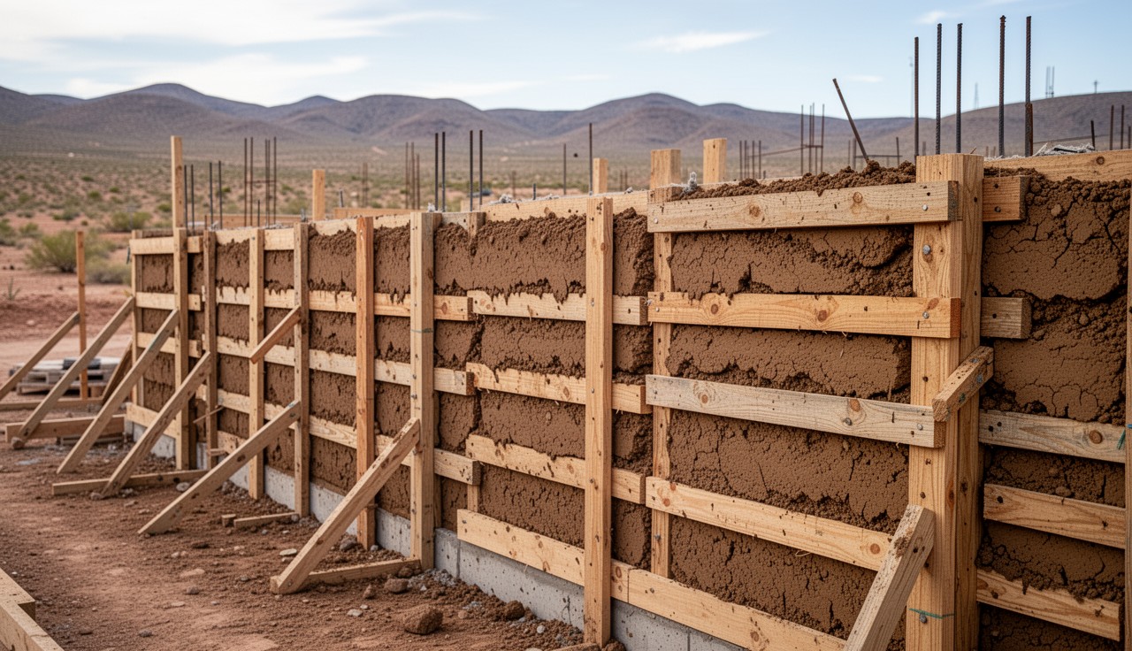
4. Rammed Earth — Forms, Lifts, and Compaction
Rammed earth produces a different wall than adobe. Instead of individual bricks laid in courses, rammed earth walls are monolithic — built in place by compacting moist soil inside formwork. The result is a dense, layered wall that shows horizontal strata where each lift was compacted. Architecturally, rammed earth walls are striking. Structurally, they are superior to adobe in compressive strength.
Formwork
Rammed earth forms must withstand the lateral pressure of compaction without deflecting. They are more substantial than concrete forms because the compaction force is applied directly against the form face.
**Plywood forms:**
- 3/4-inch exterior-grade plywood (CDX minimum, marine-grade preferred).
- Reinforced with 2x4 or 2x6 walers (horizontal stiffeners) on 12-inch centers.
- Through-bolted with 1/2-inch threaded rod at 24-inch spacing (both horizontal and vertical).
- Form height: 24–36 inches per pour. Taller forms are possible but increase lateral pressure and require heavier bracing.
- Form length: 8–12 feet per section is practical. Longer sections are unwieldy.
**Steel forms:**
- 3/16-inch or 1/4-inch steel plate with angle-iron stiffeners.
- Heavier to handle but reusable for hundreds of pours.
- Standard for commercial rammed earth construction.
- Can be rented from specialty suppliers in the Southwest.
**Form release:** Diesel fuel, used motor oil, or commercial form release oil. Apply before each pour. Rammed earth sticks to bare wood or steel and will tear the wall surface on removal.
Compaction Process
1. **Prepare the soil mix.** Same soil requirements as adobe (15–30% clay, 50–70% sand). Moisture content is critical and lower than adobe — the mix should feel barely damp. Squeeze a handful: it should hold together in a clump but break cleanly when snapped in half. No water should be visible. If water squeezes out, the mix is too wet. If it crumbles and will not clump, it is too dry. 2. **Place the first lift.** Shovel or pour loose soil into the form to a depth of 6–8 inches (loose). This will compact to 4–6 inches. 3. **Compact.** Use a rammer — pneumatic or manual — to compact the soil in systematic passes. Work from the edges inward to avoid pushing soil away from the form faces.
**Compaction tools:**
| Tool | Weight | Compaction Rate | Best For | |---|---|---|---| | Manual tamper (flat steel plate on wooden handle) | 15–25 lbs | 10–15 sq ft/hour | Small projects, tight spaces, single-person operation | | Pneumatic backfill tamper (Bosch, Ingersoll Rand) | 25–35 lbs tool weight | 30–50 sq ft/hour | Most rammed earth projects. Standard tool of the trade. | | Pneumatic pole tamper | 15–20 lbs | 20–40 sq ft/hour | Deep forms where a flat tamper cannot reach the form face |
4. **Assess compaction.** A properly compacted lift produces a distinct change in sound — from a dull thud (loose soil) to a higher-pitched ring (compacted soil). The surface should show a slight sheen from clay particles being compressed. If the tamper bounces, the lift is fully compacted. 5. **Repeat.** Add the next lift (6–8 inches loose), compact, and continue until the form is full. Each compacted lift will be visible as a distinct horizontal line in the finished wall. These lines are the signature of rammed earth construction. 6. **Strip forms.** Remove forms after compaction is complete. The wall is self-supporting immediately — it does not need to cure in the form.
Compressed Stabilized Earth Blocks (CSEB)
CSEB occupies a middle ground between adobe and rammed earth. Moist soil is placed in a manual or hydraulic press and compressed under high force (200–2000 psi applied pressure) to produce a uniform, dense block. The blocks are laid in courses like adobe but have the density and strength profile of rammed earth.
**CSEB presses:**
- **Manual lever press (Auram, Cinva-Ram):** 200–600 psi applied pressure. Produces blocks with 400–800 psi compressive strength (with 5–8% cement stabilization). One operator produces 200–400 blocks per day.
- **Hydraulic press:** 1000–2000 psi applied pressure. Produces blocks with 800–1500 psi compressive strength. Faster but requires diesel or electric power and costs $3,000–15,000 for the press.
CSEB blocks require the same soil composition as adobe and rammed earth. They benefit more from cement stabilization than either method because the high compaction pressure drives cement paste into micropores between soil particles, creating a denser bond matrix.
5. Foundation — Moisture Is the Enemy
Earth walls are strong in compression. They are weak against moisture. Every failure mode in earthen construction traces back to water: water wicking up from the ground, water splashing at the base, water penetrating through cracks, or water pooling on a flat roof. The foundation exists to divorce the wall from the ground.
Stem Wall
The stem wall is a conventional masonry or concrete wall that raises the bottom of the earthen wall above grade. Minimum height: **6 inches above finished grade** per most codes, but **12–18 inches is standard practice** in the Southwest for good reason — rain splash, irrigation overspray, and grade changes all conspire to wet the base of the wall.
**Materials:**
- Poured concrete (3000 psi minimum) — most common.
- Concrete masonry units (CMU) filled with grout.
- Stone (historically used, still appropriate for rural construction).
**Width:** The stem wall must be at least as wide as the earthen wall above it. For a 14-inch-wide adobe wall, the stem wall is 16 inches wide (allowing 1 inch of overhang on each side for the plaster base).
Gravel Drainage
Below the stem wall, a gravel drainage course prevents water from pooling under the foundation.
1. Excavate the foundation trench to below frost line (see below). 2. Lay 4 inches of compacted, well-graded gravel (3/4-inch minus) at the bottom of the trench. 3. Install a 4-inch perforated drain pipe on the gravel bed, sloped at 1/4 inch per foot to daylight or a dry well. 4. Cover the pipe with filter fabric and fill around the foundation with gravel, not backfill soil.
Damp-Proof Course (DPC)
A physical moisture barrier between the stem wall and the earthen wall. This is non-negotiable. Without a DPC, ground moisture wicks up through the concrete or stone by capillary action and saturates the base of the earthen wall, causing erosion from the inside.
**Options:**
- Two layers of 30-lb asphalt felt (tar paper), lapped 6 inches at seams.
- HDPE sheeting (6-mil minimum), lapped and sealed.
- Bituminous coating on the top of the stem wall, covered with polyethylene.
Frost Line
Foundation depth must reach below the local frost line to prevent heaving. Earthen walls, unlike wood-frame walls, cannot flex — any foundation movement causes cracking.
| Region | Approximate Frost Line Depth | |---|---| | Southern Texas, Southern Arizona | 0–6 inches (often no frost line) | | Central Texas (Austin, San Antonio) | 6–12 inches | | Northern New Mexico (Santa Fe, Taos) | 24–36 inches | | Colorado Front Range | 36–48 inches |
Check with your local building department for the official frost depth. Footings should extend a minimum of 6 inches below the frost line.
6. Wall Construction — Laying, Bonding, Rough-In
Adobe Wall Construction
**Bond Patterns:** Adobe walls use running bond (each brick overlaps the course below by half a brick length) or stack bond (bricks aligned vertically — weaker, only for non-load-bearing partitions). At corners, bricks from one wall interlock with bricks from the adjacent wall in alternating courses, creating a mechanical key.
**Mortar:** Adobe mortar is the same material as the bricks — mud. Mix the same soil used for the bricks, slightly wetter (it should trowel easily). Mud mortar joints should be 1/2 to 3/4 inch thick. Thicker joints waste material and create weak planes.
For stabilized construction, add 5% Portland cement to the mortar mix. Cement mortar is stronger than the bricks themselves, which creates a potential problem: in a seismic event, you want failure to occur in the mortar joints (which can be repaired) rather than through the bricks (which require replacement). For this reason, New Mexico's code specifies that mortar strength should not exceed brick strength by more than 50%.
**Mortar for rammed earth repairs:** If a rammed earth wall needs patching where forms did not fill completely, use the same soil mix as the wall, wetted to a stiff paste, and pack it firmly into the void.
Wall Thickness
- **Minimum for load-bearing walls:** 10 inches (NMAC 14.7.4).
- **Standard for single-story residential:** 14 inches (one brick length laid flat).
- **Optimal for thermal mass in hot-arid climates:** 18–24 inches. At 24 inches, the thermal lag exceeds 10 hours — sufficient to completely invert the daily temperature cycle.
- **Rammed earth minimum:** 12 inches. Standard residential: 18–24 inches.
Maximum Wall Height
- **Unstabilized adobe:** 10 times wall thickness, maximum. A 14-inch wall can be 140 inches (11.7 feet) tall. Taller walls require engineering review.
- **Stabilized adobe/rammed earth:** height-to-thickness ratios up to 12:1 are common in engineered construction.
Lintels and Headers
Every door and window opening requires a lintel — a horizontal beam that transfers the load above the opening to the wall on either side.
**Lintel materials:**
- Rough-sawn timber (6x8 minimum for openings up to 4 feet; 6x10 or 6x12 for openings up to 8 feet). Historically, this is the standard. Select rot-resistant species: juniper, cypress, mesquite, or pressure-treated Douglas fir.
- Reinforced concrete lintels — poured in place or precast. These are the code-compliant choice for permitted construction.
- Steel angle iron — L-shaped steel (minimum 4x4x1/4 inch for openings up to 4 feet).
**Lintel bearing:** The lintel must extend a minimum of 8 inches (one-half brick length) beyond each side of the opening, resting on the full width of the wall.
Window and Door Bucks
Bucks are the wooden frames set into the wall during construction to create the rough opening for windows and doors. They are not the finished window frame — they are the structural frame that the wall is built around.
**Construction:**
- 2x material (2x10, 2x12, or 2x14 depending on wall thickness), ripped to match wall width exactly.
- Assemble into a rectangle matching the rough opening size.
- Anchor to the wall with rebar pins: drill 1/2-inch holes through the buck and drive 18-inch lengths of #4 rebar through the holes and into the adobe or rammed earth as the wall rises.
- Plumb and level the buck before the wall reaches the lintel height. Adjusting a buck after the wall is built is destructive.
Electrical and Plumbing
**Electrical:** Run conduit (EMT or PVC) vertically inside the wall during construction. Lay the conduit against the form face (rammed earth) or between brick courses (adobe) and build the wall around it. Outlet boxes mount flush with the inside wall face. Do not chase (cut channels into) a finished earth wall for wiring — it weakens the wall and is nearly impossible to patch invisibly.
**Plumbing:** Keep all supply and drain plumbing in interior frame walls, not in earth walls. If a pipe must penetrate an earth wall, sleeve it in PVC pipe 2 sizes larger than the supply line to allow for expansion and to create a replaceable pathway. Never embed copper supply lines directly in earth — the lime in stabilized earth corrodes copper over decades.
7. Roofing — Bond Beam, Structure, Drainage
Bond Beam
The bond beam is a continuous reinforced concrete beam poured on top of the finished wall. It serves three functions: it ties the tops of all walls together as a rigid ring, it distributes roof loads evenly across the wall, and it provides an anchor point for the roof structure.
**Construction:** 1. Build a form on top of the finished wall (2x6 or 2x8 lumber, forming a channel the full width of the wall). 2. Place two continuous runs of #4 rebar inside the form, supported on chairs to maintain 1.5-inch cover from all sides. 3. At corners, bend the rebar around the corner with a minimum 12-inch overlap, wired to the adjacent bar. 4. Set anchor bolts (1/2-inch J-bolts, 10 inches long) at 48-inch spacing and at every location where a roof member will bear on the wall. 5. Pour the bond beam with 3000 psi concrete. Vibrate or rod to eliminate voids.
The bond beam typically adds 6–8 inches to the wall height. Plan for this in your wall height calculations.
Traditional Roof: Vigas and Latillas
The traditional Southwest roof system uses round timber beams (vigas) spanning from wall to wall, with smaller poles (latillas) or split cedar (rajas) laid across the vigas to create the roof deck.
- **Vigas:** Peeled logs, 8–12 inches in diameter, spanning up to 16 feet (longer spans require engineered review). Species: ponderosa pine, Douglas fir, or spruce. The vigas extend through the wall to the exterior, creating the characteristic protruding beam ends of Pueblo Revival architecture.
- **Latillas:** 2–3 inch diameter poles laid across the vigas at 2–3 inch spacing. Traditionally peeled aspen, willow, or cedar.
- **Roof build-up over latillas:** 2 inches of packed earth or rigid insulation, a waterproof membrane (EPDM rubber or modified bitumen), and 2–3 inches of earth topping for thermal mass and UV protection of the membrane.
Conventional Truss or Rafter Systems
Any conventional roof system works on earthen walls as long as it bears on the bond beam. Prefabricated trusses, site-built rafters, or SIPs (structural insulated panels) all attach to the bond beam through the embedded anchor bolts.
Pitched roofs are simpler to waterproof than flat roofs and are recommended in climates with any significant rainfall. A minimum 4:12 pitch with standing-seam metal roofing is the most durable, lowest-maintenance option for earthen construction.
Flat Roof Drainage
Flat roofs (slope < 2:12) on earthen buildings require aggressive drainage. Standing water on a flat roof above earth walls is a structural emergency — the water weight adds load and any leak delivers moisture directly into the wall.
- **Minimum slope:** 1/4 inch per foot toward scuppers or internal drains.
- **Scuppers:** Sheet-metal-lined openings through the parapet wall, directing water to canales (spouts that project from the wall) or downspouts.
- **Canales:** Traditional Southwest drainage — carved or formed channels that project 12–18 inches from the wall, directing water away from the base. Metal-lined for longevity.
8. Finishing — Plaster, Stucco, and Sealers
Unfinished earthen walls erode. Rain, wind, freeze-thaw cycles, and UV exposure all degrade exposed earth surfaces. Every earthen wall needs a protective finish. The choice of finish determines how the wall interacts with moisture — and getting this wrong is the single most common cause of premature wall failure.
Earthen Plaster (Mud Plaster)
The most traditional and most compatible finish. Earthen plaster breathes with the wall — it absorbs and releases moisture at the same rate as the wall material, preventing trapped moisture.
**Mix:** Clay slip (clay-rich soil mixed with water to a heavy cream consistency) + fine sand (ratio 1:2 to 1:3 clay slip to sand) + chopped fiber (straw, cattail fluff, or shredded paper). The fiber controls cracking, same as in adobe bricks.
**Application:** 1. Wet the wall surface thoroughly. 2. Apply a scratch coat 3/8 to 1/2 inch thick. Score the surface with horizontal grooves to key the finish coat. 3. Allow to dry completely (3–7 days depending on humidity). 4. Apply the finish coat 1/4 to 3/8 inch thick. The finish coat uses finer sand and less fiber for a smoother texture. 5. Burnish (polish) the finish coat with a smooth stone or steel trowel while it is still damp — this compresses the surface clay and creates a hard, water-resistant skin.
**Maintenance:** Mud plaster requires recoating every 3–5 years on exterior surfaces. Interior surfaces last decades.
Lime Plaster
Lime plaster is harder and more weather-resistant than mud plaster while remaining vapor-permeable (breathable). It is the standard exterior finish for earthen construction in the Southwest and Mediterranean.
**Mix:** 1 part aged lime putty (or hydrated Type S lime) to 3 parts sharp sand. No cement. Cement makes the plaster too hard and too brittle — it cracks and traps moisture behind it.
**Application:** 1. Dampen the wall. 2. Apply scratch coat 3/8 inch thick. Score for key. 3. Cure: mist with water daily for 3 days (lime sets by carbonation, not hydration — it needs moisture and CO2). 4. Apply brown coat 3/8 inch thick. Cure 3 days. 5. Apply finish coat 1/8 to 1/4 inch thick. Can be tinted with natural pigments (iron oxide for terra cotta, manganese dioxide for black, titanium dioxide for white).
Lime plaster self-heals hairline cracks through continued carbonation — dissolved calcium hydroxide migrates into cracks and re-crystallizes as calcium carbonate.
Cement Stucco
Cement stucco (Portland cement + sand) is harder than lime plaster and more weather-resistant in the short term. It is also the most common cause of earthen wall failure.
**The problem:** Cement stucco is vapor-impermeable — it traps moisture inside the wall. In climates with any rainfall, moisture enters the wall through cracks in the stucco, condenses inside the wall, and cannot escape outward through the stucco layer. The wall stays wet, the base erodes from the inside, and the stucco shell eventually separates from a hollow wall. This failure mode is well-documented in historic adobe buildings that were "improved" with cement stucco (Tolles et al., 2000, *Seismic Stabilization of Historic Adobe Structures*, Getty Conservation Institute).
**When cement stucco is appropriate:** Only on cement-stabilized walls in arid climates with less than 10 inches of annual rainfall. Even then, lime plaster is usually the better choice.
Sealers
**Linseed oil:** Boiled linseed oil (not raw — raw linseed takes months to cure) applied to interior earthen plaster creates a hard, matte-sheen surface that resists dusting and light abrasion. Apply 2–3 coats, thinning the first coat 50:50 with mineral spirits to improve penetration. Each coat must dry 24 hours before the next.
**Sodium silicate (waterglass):** A liquid glass treatment that penetrates the surface 1/4 to 1/2 inch and hardens by forming an amorphous silica matrix within the clay structure. Reduces dusting and improves surface hardness without changing appearance. Apply as a 1:4 dilution (sodium silicate to water) in 2 coats.
9. Thermal Performance — Why R-Value Gets It Wrong
The building industry evaluates wall thermal performance by R-value: resistance to steady-state heat flow. A 2x6 wall with fiberglass batt insulation is R-19. A 2x6 wall with closed-cell spray foam is R-38. A 14-inch adobe wall is R-2.8 (at R-0.2 per inch).
By R-value alone, adobe is a terrible insulator. This is also why R-value is the wrong metric for mass walls.
Steady-State vs. Dynamic Conditions
R-value measures heat flow under steady-state conditions — a constant temperature difference across the wall, sustained indefinitely. This is a useful model for cold climates where the outside temperature stays below the inside temperature for weeks at a time (Minneapolis in January, for example). In those conditions, the wall's only job is to resist continuous heat loss, and R-value accurately predicts energy consumption.
In climates with significant diurnal temperature swings — where the outside temperature oscillates above and below the desired interior temperature within a single 24-hour cycle — steady-state conditions never exist. The temperature differential across the wall reverses direction every 12 hours. Under these conditions, thermal mass becomes the dominant variable, not thermal resistance.
The Flywheel Effect
A mass wall stores heat as it passes through. The rate of passage is slow — approximately 1 inch per hour in earth walls (Balcomb, 1992). This creates a time delay between the exterior temperature peak and the interior temperature response.
**Example: Tucson, Arizona, summer day.**
- Exterior high: 105°F at 3:00 PM.
- Exterior low: 72°F at 5:00 AM.
- Diurnal swing: 33°F.
In a 24-inch adobe wall:
- The 3:00 PM heat peak enters the exterior face immediately.
- The heat wave reaches the interior face approximately 12 hours later — at 3:00 AM, when exterior temperatures are in the mid-70s.
- The wall is now radiating stored heat into the interior, but the exterior has dropped 30+ degrees, so the wall simultaneously begins absorbing coolness from outside.
- By 3:00 PM the next day, the "cool wave" from the previous night reaches the interior — just as exterior temperatures peak again.
The result: interior temperatures fluctuate between approximately 72°F and 82°F despite a 33°F exterior swing. The wall is acting as a thermal flywheel, smoothing out the temperature oscillation and maintaining comfort without any mechanical input.
Climate Suitability
Thermal mass walls are most effective where:
- Diurnal temperature swing exceeds 27°F (15°C) — the greater the swing, the greater the benefit (Givoni, 1994).
- Summer nighttime lows drop below 75°F — if nights stay hot, the wall never discharges its stored heat.
- Winter conditions include sunny days — south-facing mass walls absorb solar radiation during the day and release it inward at night.
- Humidity is low — high humidity reduces radiative cooling at night, limiting the wall's ability to discharge heat.
**Where mass walls work well:** Arizona, New Mexico, West Texas, Colorado, Utah, inland California, the Mediterranean, the Middle East, highland Mexico, the Andes, Central Asia, the Australian Outback.
**Where mass walls work poorly without supplemental insulation:** Pacific Northwest (low diurnal swing, high humidity), Gulf Coast (low diurnal swing, extreme humidity), northern Midwest (diurnal swing exists but baseline winter temperatures are too cold for mass alone — the wall simply cannot store enough heat from weak winter sun).
**Hybrid approach:** In cold climates, exterior insulation applied outside a mass wall preserves the thermal mass benefit while adding R-value. The insulation stops heat loss; the mass stabilizes interior temperature. This is the approach used in modern rammed earth construction in Colorado and Montana.
10. Code and Permits — Building Legal
IRC Appendix S
The 2021 International Residential Code (IRC) includes Appendix S: Earthen Construction. This appendix provides prescriptive requirements for adobe, rammed earth, and compressed earth block construction in single-family residential buildings. Appendix S is an optional appendix — local jurisdictions must adopt it for it to have legal force.
Key provisions of Appendix S:
- Minimum compressive strength: 300 psi (adobe and CEB), 300 psi (rammed earth).
- Maximum unsupported wall height: 10x wall thickness.
- Minimum wall thickness: 10 inches for load-bearing walls.
- Moisture protection: stem wall, DPC, and eave overhang or wall coating required.
- Bond beam required at top of all load-bearing walls.
New Mexico Earthen Building Code (NMAC 14.7.4)
New Mexico has the most developed earthen building code in the United States. NMAC 14.7.4 has been in continuous use since 1991 and covers:
- Soil testing requirements (ASTM D4318 for Atterberg limits, ASTM C67 for brick compression).
- Stabilized and unstabilized adobe.
- Rammed earth.
- Burned adobe (a fired earth product unique to the Southwest).
- Mortar specifications.
- Foundation and stem wall requirements.
- Wall height and thickness ratios.
- Seismic reinforcement for earthen walls.
If you are seeking a building permit for earthen construction in a jurisdiction that has not adopted Appendix S, the New Mexico code is the strongest reference document to present to your building official. Many jurisdictions will accept an engineer's stamp on plans that reference NMAC 14.7.4 as the design standard.
Uniform Building Code (UBC) Standards
Pre-IRC UBC standards 24-15 (adobe) and 24-16 (rammed earth) are still referenced in some older jurisdictions. These have been largely superseded by IRC Appendix S but remain valid engineering references.
Practical Permitting Strategy
1. Check whether your jurisdiction has adopted IRC Appendix S. If yes, use its prescriptive provisions. 2. If not, hire a licensed structural engineer familiar with earthen construction. The engineer stamps the plans, calculates loads, and specifies soil testing per ASTM standards. Most building officials will issue a permit for engineered construction regardless of material type. 3. If neither option is available, consider building a non-habitable structure (workshop, barn, storage building) first. Many jurisdictions exempt non-habitable agricultural buildings from residential codes. This gives you a completed project to show the building inspector and demonstrate competence before proposing a residence. 4. Document everything: soil test results, brick compression tests, foundation details, bond beam reinforcement. Inspectors who have never seen earthen construction will be more confident if your documentation exceeds code requirements.
11. Sources
- Balcomb, J.D. (1992). *Passive Solar Buildings*. MIT Press.
- Givoni, B. (1994). *Passive and Low Energy Cooling of Buildings*. Wiley.
- Heathcote, K.A. (1995). Durability of earthwall buildings. *Building Research & Information*, 23(2), 101–108.
- Houben, H. & Guillaud, H. (1994). *Earth Construction: A Comprehensive Guide*. CRATerre-EAG / Intermediate Technology Publications.
- Jaquin, P.A., Augarde, C.E., & Gerrard, C.M. (2004). Analysis of historic rammed earth construction. *Construction and Building Materials*, 18(4), 281–286.
- McHenry, P.G. (1984). *Adobe and Rammed Earth Buildings: Design and Construction*. University of Arizona Press.
- Minke, G. (2006). *Building with Earth: Design and Technology of a Sustainable Architecture*. Birkhauser.
- Tolles, E.L., Kimbro, E.E., Webster, F.A., & Ginell, W.S. (2000). *Seismic Stabilization of Historic Adobe Structures: Final Report of the Getty Seismic Adobe Project*. Getty Conservation Institute.
- Walker, P., Keable, R., Martin, J., & Maniatidis, V. (2005). *Rammed Earth: Design and Construction Guidelines*. BRE Press.
- International Code Council. (2021). *International Residential Code*, Appendix S: Earthen Construction.
- New Mexico Construction Industries Division. (2021). *New Mexico Earthen Building Materials Code*, NMAC 14.7.4.
- ASTM C67/C67M. *Standard Test Methods for Sampling and Testing Brick and Structural Clay Tile*.
- ASTM D4318. *Standard Test Methods for Liquid Limit, Plastic Limit, and Plasticity Index of Soils*.
`[practical-skills]` `[facility-design]` `[advanced]`