plants
Battery Bank Design and Construction
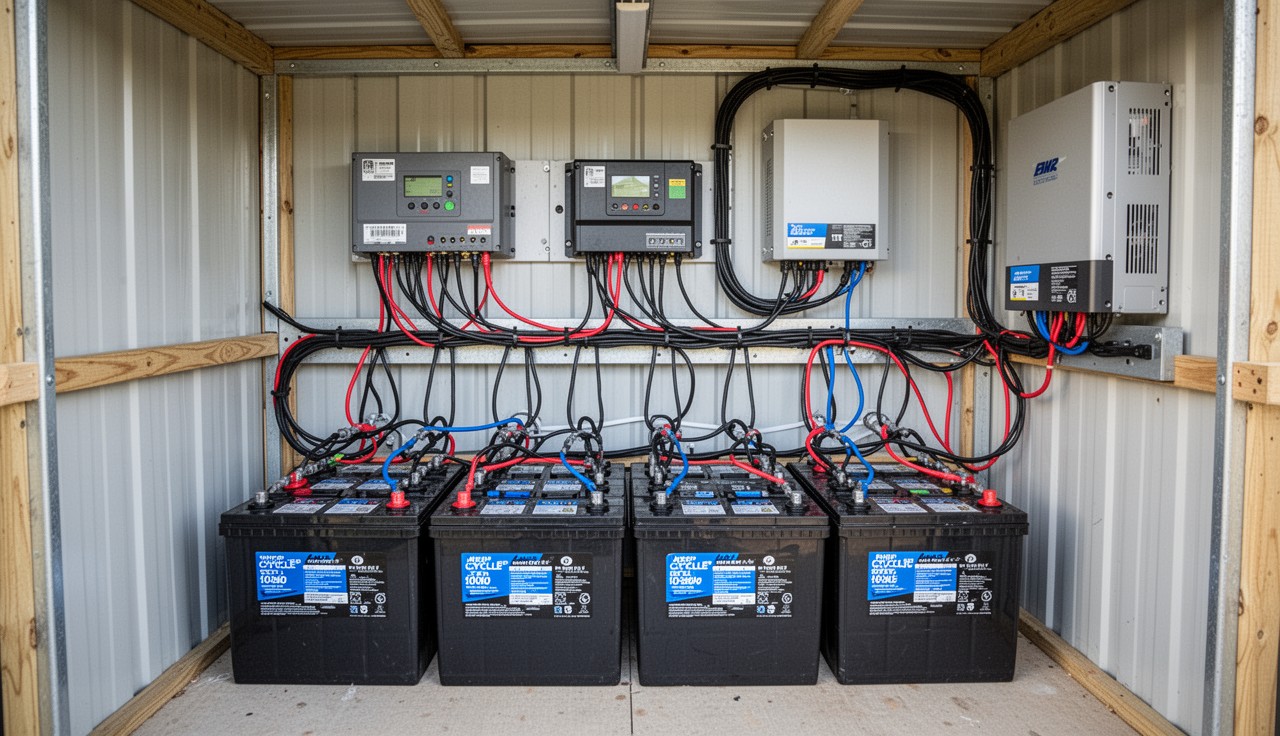
Design and build an off-grid battery bank: battery chemistry comparison, electrical fundamentals, system sizing, wiring, and safe construction.
Content Extraction Summary
Hook Options
- A 48V LiFePO4 battery bank stores the same usable energy as a lead-acid bank three times its weight and five times its volume — and outlasts it by a factor of ten in cycle life.
- The single most common failure in DIY battery banks is not bad cells or cheap BMS units — it is undertorqued terminal connections that create resistance hot spots, arc, and eventually start fires.
- Peukert's exponent means a 400Ah lead-acid battery rated at the 20-hour rate delivers only about 250Ah at a 5-hour discharge rate — a 37% capacity loss that most system designers never account for.
Key Mechanism
A battery bank is a series-parallel arrangement of electrochemical cells that stores DC energy for later use. Series connections increase voltage while maintaining the same capacity. Parallel connections increase capacity while maintaining the same voltage. The bank's usable capacity is determined not by its nameplate rating but by its chemistry-specific depth of discharge limit, the Peukert effect (lead-acid only), temperature derating, and the inverter's low-voltage cutoff setting.
Misconception to Correct
Most off-grid builds treat battery selection as a cost-per-amp-hour decision. Flooded lead-acid looks cheapest at $150/kWh vs $400/kWh for LiFePO4. But lead-acid at 50% DOD delivers 500–800 cycles. LiFePO4 at 80% DOD delivers 3,000–5,000 cycles. Over a 15-year system life, lead-acid costs $0.25–$0.40/kWh/cycle while LiFePO4 costs $0.08–$0.12/kWh/cycle. The cheap battery is the expensive one.
Practical Application
Size a battery bank by calculating your daily watt-hour load, dividing by system voltage to get amp-hours, then derating for DOD, temperature, and autonomy days. A household using 5 kWh/day on a 48V system needs 104Ah of raw capacity — derated to 50% DOD for lead-acid that becomes a 208Ah bank, or derated to 80% DOD for LiFePO4 that becomes a 130Ah bank. Then add autonomy days (typically 2–3 for solar systems) and you have your minimum bank size.
Citation-Ready Claims
- [LiFePO4 cycle life 3,000–5,000 cycles at 80% DOD] → [vs lead-acid 500–800 cycles at 50% DOD] → [Battery University, Electrochemical Society papers]
- [Peukert effect reduces lead-acid usable capacity 30–40% at high discharge rates] → [C/5 vs C/20 rate comparison] → [Peukert, W. (1897), IEEE Transactions on Energy Conversion]
- [NEC 240.4 requires conductor ampacity not less than the noncontinuous load plus 125% of the continuous load] → [National Electrical Code 2023 Edition]
- [Class T fuses rated for DC interrupt capacity up to 20,000A at 125VDC] → [Required for lithium battery protection per inverter manufacturer specs] → [Littelfuse / Mersen data sheets]
- [Hydrogen gas LEL 4% by volume in air] → [Ventilation requirement for flooded lead-acid enclosures] → [IEEE 484-2019, NFPA 1 Chapter 52]
Battery Bank Design and Construction
*Pure Euphoria Botanicals · Nored Farms · Austin, Texas*
1. Introduction
Battery storage is the bottleneck in every off-grid and hybrid power system. Solar panels are cheap. Wind turbines are mature. Charge controllers are commodity electronics. But the battery bank determines how much energy you can actually use when the source is not producing — and it is the most expensive, heaviest, most maintenance-intensive, and most failure-prone component in the system.
The reason is thermodynamic. Converting electrical energy to chemical energy and back involves losses at every stage: charge acceptance efficiency, internal resistance heating, self-discharge, and degradation of active electrode materials over repeated cycles. No battery chemistry escapes these constraints. The engineering question is not which battery is best in the abstract. It is which chemistry, topology, and protection system delivers the lowest cost per usable kilowatt-hour over the system's intended life at your site's temperature range.
**Most DIY battery bank failures trace to five causes:** undersizing (the bank cannot meet the load without exceeding safe DOD), poor connections (undertorqued terminals that create high-resistance joints), inadequate fusing (a short circuit delivers thousands of amps with no interruption device), wrong charging profile (lead-acid floated too low sulfates; lithium overcharged without BMS trips catch fire), and no temperature compensation (a battery rated at 77°F loses 20–30% capacity at 32°F).
This document covers chemistry selection, electrical design, physical construction, protection systems, charging, maintenance, and scaling. A reader with basic electrical knowledge should be able to design, build, and commission a battery bank from this document alone.
2. Battery Chemistry Comparison
Six chemistries dominate stationary storage. Each has a specific use case where it wins on cost-per-cycle, weight, temperature tolerance, or maintenance burden.
Chemistry Overview Table
| Parameter | Flooded Lead-Acid (FLA) | AGM | Gel | LiFePO4 (LFP) | Sodium-Ion (Na-ion) | Nickel-Iron (NiFe) | |---|---|---|---|---|---|---| | **Nominal cell voltage** | 2.0V | 2.0V | 2.0V | 3.2V | 3.1V | 1.2V | | **Typical system config** | 24 cells = 48V | 24 cells = 48V | 24 cells = 48V | 16 cells = 51.2V | 16 cells = 49.6V | 40 cells = 48V | | **Cost per kWh (2024–2026)** | $100–$200 | $200–$350 | $250–$400 | $300–$500 | $150–$250 | $400–$800 | | **Cycle life at rated DOD** | 500–1,500 @ 50% | 400–800 @ 50% | 500–1,000 @ 50% | 3,000–6,000 @ 80% | 2,000–4,000 @ 80% | 10,000+ @ 80% | | **Max recommended DOD** | 50% | 50% | 50% | 80–90% | 80–90% | 80% | | **Round-trip efficiency** | 75–85% | 80–85% | 80–85% | 92–98% | 85–92% | 65–75% | | **Self-discharge/month** | 3–5% | 1–3% | 1–3% | 1–3% | <1% | 20–40% | | **Weight per kWh** | 25–35 kg | 25–35 kg | 25–35 kg | 6–10 kg | 10–15 kg | 40–60 kg | | **Temperature range** | -20°C to 50°C | -20°C to 50°C | -20°C to 45°C | -20°C to 60°C (charge >0°C) | -30°C to 60°C | -30°C to 60°C | | **Maintenance** | High (watering, equalization) | None | None | Low (BMS monitoring) | Low | High (watering) | | **Hydrogen off-gassing** | Yes — requires ventilation | Minimal (sealed) | Minimal (sealed) | No | No | Yes | | **Thermal runaway risk** | No | Low | Low | Very low | Very low | No |
Chemistry Deep Dive
**Flooded lead-acid** remains the default for budget builds and rural installations where replacement batteries are locally available. The Trojan T-105 (6V, 225Ah at C/20) has been the standard golf cart / off-grid battery for decades. Expect 800–1,200 cycles at 50% DOD with proper maintenance. The catch: "proper maintenance" means checking specific gravity monthly with a hydrometer, adding distilled water every 2–6 weeks depending on charge rates, performing equalization charges every 30–90 days, and cleaning terminal corrosion. Most people do not maintain them. Unmaintained FLA batteries last 2–3 years instead of 5–7.
**AGM (Absorbed Glass Mat)** eliminates the water maintenance of FLA at higher cost. The electrolyte is held in fiberglass mat separators. No free liquid, no spills, minimal gassing, can be mounted in any orientation. But AGM is less tolerant of overcharging than FLA — the gas recombination system fails if charging voltage is too high, venting electrolyte that cannot be replaced. AGM also has lower cycle life than well-maintained FLA. Use AGM when the battery bank must be in a living space, when maintenance access is limited, or when the system will be unattended for long periods.
**Gel** batteries use silica-mixed electrolyte that forms a gel. Similar advantages to AGM (sealed, no maintenance) with better deep-cycle tolerance and longer life in hot climates. Gel is sensitive to charging voltage — must not exceed 14.1V per 12V battery (2.35V/cell). Overcharging creates voids in the gel that permanently reduce capacity. The charging restriction makes gel a poor match for solar systems with variable charge rates unless the charge controller has a specific gel profile.
**LiFePO4 (lithium iron phosphate)** is the current standard for new builds above the tightest budgets. The chemistry uses an iron phosphate cathode that is thermally stable — it does not experience thermal runaway under normal abuse conditions, unlike lithium cobalt oxide (phones, laptops) or lithium nickel manganese cobalt (EVs). LFP cells deliver a flat discharge curve (holds ~3.2V for 80% of the discharge), accept fast charging (0.5C–1C standard, 2C+ possible), and lose minimal capacity at moderate discharge rates (no Peukert effect). The tradeoff: LFP cells must not be charged below 0°C — lithium plating on the anode permanently damages the cell. A heated battery compartment or low-temperature cutoff BMS is mandatory in cold climates.
**Sodium-ion** is the emerging chemistry to watch. CATL announced first-generation sodium-ion cells in 2021 with 160 Wh/kg energy density. By 2025–2026, several manufacturers ship 200+ Wh/kg prismatic cells. Sodium is abundant (table salt), eliminating lithium supply chain risk. Na-ion performs well at low temperatures (-30°C charge capable) and has no lithium plating risk. Cycle life projections are 2,000–4,000 cycles at 80% DOD. Current downsides: lower energy density than LFP (fewer Wh per kg), limited availability, fewer BMS options, and less field data. This chemistry will likely become the price/performance leader for stationary storage within 3–5 years.
**Nickel-iron** batteries are the cockroach of battery chemistries — nearly indestructible. Thomas Edison patented the design in 1901. Cycle life exceeds 10,000 cycles. They tolerate deep discharge, overcharge, undercharge, freezing, and years of neglect. The problems: low round-trip efficiency (65–75%), extreme self-discharge (20–40% per month), heavy, expensive, and require regular watering. NiFe is viable only for systems with excess generation capacity where efficiency losses do not matter and the battery must last 30+ years without replacement.
3. Electrical Fundamentals
Series vs. Parallel
**Series connections** add voltages. Four 12V, 100Ah batteries in series produce a 48V, 100Ah bank (4.8 kWh).
**Parallel connections** add capacities. Four 12V, 100Ah batteries in parallel produce a 12V, 400Ah bank (4.8 kWh).
**Series-parallel** combines both. Eight 12V, 100Ah batteries — two parallel strings of four in series — produce a 48V, 200Ah bank (9.6 kWh).
**Critical rule:** All batteries in a series string must be the same chemistry, manufacturer, model, and ideally the same production batch. Mismatched batteries in a series string will diverge in state of charge, causing the weakest cell to be overdischarged and the strongest to be overcharged. This accelerates degradation and creates safety hazards.
**Parallel strings** are more forgiving but still require matching. Mismatched parallel strings will circulate current between each other as the higher-voltage string charges the lower-voltage string, generating waste heat and accelerating aging.
Capacity Math
Nameplate capacity is rated at a specific discharge rate:
- **C/20 rate:** Battery delivers its rated capacity over 20 hours. A 200Ah battery at C/20 delivers 10A for 20 hours.
- **C/10 rate:** Same battery delivers higher current (20A) but for fewer than 10 hours due to losses.
- **C/5 rate:** Even higher current (40A), even fewer usable amp-hours.
Peukert Effect (Lead-Acid Only)
Peukert's law describes the capacity loss in lead-acid batteries at higher discharge rates. The relationship is:
**t = H × (C / (I × H))^k**
Where:
- t = actual discharge time (hours)
- H = rated discharge time (typically 20 hours)
- C = rated capacity at H-hour rate
- I = actual discharge current
- k = Peukert exponent (1.1–1.3 for lead-acid; 1.0 = ideal battery)
**Worked example:** A Trojan T-105, rated 225Ah at C/20 (11.25A for 20 hours), with Peukert exponent k = 1.25.
At 45A discharge (C/5 rate):
- t = 20 × (225 / (45 × 20))^1.25
- t = 20 × (0.25)^1.25
- t = 20 × 0.177
- t = 3.54 hours
- Usable capacity = 45A × 3.54h = 159Ah (not 225Ah)
That is a 29% capacity loss just from drawing current faster. At C/2 rates (heavy inverter loads), losses exceed 40%.
**LiFePO4 has no meaningful Peukert effect.** A 200Ah LFP cell delivers approximately 200Ah whether discharged at C/20 or C/2. This is one of the most significant practical advantages of lithium over lead-acid.
C-Rate
C-rate describes charge or discharge current relative to battery capacity:
- **1C** = current equal to the battery's capacity (200A for a 200Ah battery)
- **0.5C** = half the capacity (100A for 200Ah)
- **0.1C** = one-tenth (20A for 200Ah)
Most lead-acid batteries should not be charged above 0.1C–0.2C (bulk phase). LiFePO4 accepts 0.5C–1C standard charge rates. Exceeding the manufacturer's rated C-rate generates excess heat and accelerates degradation.
4. System Design
Step 1: Load Analysis
Catalog every electrical load. Measure actual consumption with a Kill-A-Watt meter or clamp ammeter — nameplate ratings overstate actual draw.
| Load | Watts | Hours/Day | Wh/Day | |---|---|---|---| | LED lighting (whole house) | 80 | 6 | 480 | | Refrigerator (Energy Star) | 60 avg | 24 | 1,440 | | Laptop + router + modem | 65 | 10 | 650 | | Well pump (1/2 HP) | 750 | 1 | 750 | | Washing machine | 500 | 0.5 | 250 | | Ceiling fans (3×) | 120 | 8 | 960 | | Miscellaneous (phone charging, tools) | — | — | 300 | | **Total** | — | — | **4,830** |
Step 2: System Voltage Selection
| System Voltage | Best For | Wire Size Impact | Typical Inverter Size | |---|---|---|---| | 12V | Small systems <1 kW | Very heavy gauge required | 1,000–2,000W | | 24V | Medium systems 1–3 kW | Moderate gauge | 2,000–4,000W | | 48V | Large systems 3 kW+ | Smallest gauge for given power | 4,000–12,000W |
**Always choose 48V for whole-house systems.** At 5,000W load, a 12V system draws 417A (requiring 4/0 AWG cable runs), a 24V system draws 208A (2/0 AWG), and a 48V system draws 104A (2 AWG). Higher voltage means smaller cables, lower losses, and cheaper installation.
Step 3: Calculate Required Battery Capacity
**Formula:**
``` Required Ah = (Daily Wh ÷ System Voltage) ÷ Max DOD × Days of Autonomy × Temperature Derating Factor ```
**Worked example — 48V LiFePO4 system, 2 days autonomy, mild climate:**
1. Daily load: 4,830 Wh 2. System voltage: 48V 3. Raw daily Ah: 4,830 ÷ 48 = 100.6 Ah 4. DOD derating (80% for LFP): 100.6 ÷ 0.80 = 125.8 Ah 5. Autonomy (2 days): 125.8 × 2 = 251.5 Ah 6. Temperature derating (1.0 for 77°F / 25°C): 251.5 × 1.0 = 251.5 Ah 7. **Minimum bank size: 260Ah at 48V (round up to next available battery size)**
**Same system with flooded lead-acid, 3 days autonomy, 50°F average battery temp:**
1. Daily load: 4,830 Wh 2. System voltage: 48V 3. Raw daily Ah: 100.6 Ah 4. DOD derating (50% for FLA): 100.6 ÷ 0.50 = 201.2 Ah 5. Autonomy (3 days): 201.2 × 3 = 603.6 Ah 6. Temperature derating (1.11 for 50°F): 603.6 × 1.11 = 670 Ah 7. **Minimum bank size: 680Ah at 48V**
Temperature Derating Factors
| Battery Temperature | Derating Factor (multiply required Ah) | |---|---| | 80°F / 27°C | 1.00 | | 70°F / 21°C | 1.04 | | 60°F / 16°C | 1.11 | | 50°F / 10°C | 1.19 | | 40°F / 4°C | 1.30 | | 30°F / -1°C | 1.40 | | 20°F / -7°C | 1.59 |
These factors apply to lead-acid batteries. LiFePO4 shows less capacity loss with temperature but must not be charged below 32°F / 0°C without a heated enclosure.
5. Construction
Cable Sizing
Battery interconnect cables must be sized for the maximum continuous current plus a safety margin. Use the NEC 310.16 ampacity table for copper conductors at 75°C insulation rating.
| AWG | Ampacity (75°C) | Typical Application | |---|---|---| | 6 AWG | 65A | Small 12V systems, parallel jumpers | | 4 AWG | 85A | 24V moderate loads | | 2 AWG | 115A | 48V systems up to 5 kW | | 1/0 AWG | 150A | 48V systems 5–8 kW | | 2/0 AWG | 175A | 24V systems, high-current 48V | | 4/0 AWG | 230A | 12V systems, very high current |
**Use fine-stranded welding cable or battery cable** — not solid or coarse-stranded building wire. Battery terminals require flexibility to route between posts, and fine-stranded cable crimps more reliably.
**Cable length matters.** Voltage drop across battery interconnects should stay below 1%. For a 48V system at 100A with 2 AWG cable, maximum one-way cable length for 1% drop is approximately 5.5 feet. Keep battery interconnects as short as possible — 12–18 inches is standard for batteries on a rack.
Terminal Connections
**Torque specifications by terminal type:**
| Terminal Type | Torque | Tool | |---|---|---| | Lead-acid automotive post (top terminal) | 50–70 in-lb | 5/16" or 3/8" wrench | | Lead-acid stud terminal (L-16, industrial) | 95–110 in-lb | 5/16" stud: 95 in-lb; 3/8" stud: 110 in-lb | | LiFePO4 prismatic cell M6 bolt | 44–53 in-lb (5–6 Nm) | M6 socket, torque wrench | | LiFePO4 prismatic cell M8 bolt | 88–106 in-lb (10–12 Nm) | M8 socket, torque wrench | | Bus bar bolted connections | Per manufacturer spec | Calibrated torque wrench |
**Never use adjustable wrenches on battery terminals.** They round the fastener and cannot deliver consistent torque. Use a calibrated torque wrench or at minimum a box-end wrench of the correct size.
**Apply anti-oxidant compound** (Burndy Penetrox or equivalent) to all copper-to-copper and copper-to-aluminum connections before assembly. After assembly, coat exposed terminal connections with battery terminal protectant spray or liquid electrical tape to prevent corrosion.
Bus Bars
Bus bars distribute current from parallel battery strings to a single output point. Use tinned copper bus bars rated for the maximum current of all parallel strings combined.
**Minimum bus bar sizing:**
| Total System Current | Bus Bar Cross-Section | |---|---| | Up to 100A | 1/4" × 1" copper flat bar | | 100–200A | 1/4" × 1.5" copper flat bar | | 200–400A | 1/4" × 2" copper flat bar or dual 1" bars | | 400A+ | 3/8" × 2" copper flat bar or commercial bus bar assembly |
Fusing
**Every battery bank needs fusing.** A short-circuited lead-acid battery can deliver 5,000–10,000A. A LiFePO4 cell can deliver 3,000–8,000A. Without a fuse or breaker, a short circuit will vaporize cable, melt terminals, and start fires.
**Fuse types for DC battery systems:**
| Fuse Type | DC Voltage Rating | Interrupt Rating | Typical Use | |---|---|---|---| | Class T (Littelfuse JLLN/JLLS) | 125–300VDC | 20,000A | Main battery bank fuse, required by most inverter manufacturers | | ANL | 32–80VDC | 6,000A | Branch circuit fusing, parallel string fusing | | MEGA (AMG) | 32–58VDC | 2,000A | Lower-current branch circuits | | NH / DIN fuse | 250–500VDC | 50,000–100,000A | Commercial/industrial battery systems | | DC-rated breaker (Midnite Solar, Eaton) | 125–600VDC | 10,000–25,000A | Main disconnect with overcurrent protection |
**Class T fuses are mandatory for systems with high available fault current.** If the battery bank can deliver more than 6,000A in a short circuit (most lithium banks can), ANL fuses cannot safely interrupt the fault. Use Class T fuses rated for the system's maximum fault current.
**Fuse sizing:** Rate fuses at 125% of the maximum continuous current on the circuit (NEC 240.4). For a 48V, 5,000W inverter drawing 104A continuous, the fuse should be rated at 130A minimum. Use a 150A or 175A Class T fuse.
**Every parallel string needs its own fuse.** If one string develops an internal short, the other strings will dump current into the faulted string. String fuses prevent this cascade failure.
Disconnect Switches
Install a DC-rated disconnect switch between the battery bank and the inverter/charge controller. This allows the battery to be isolated for maintenance, emergency shutdown, or inverter replacement without disconnecting individual battery terminals.
**Requirements:**
- Rated for system voltage (48VDC minimum for 48V systems; use 125–250VDC rated switches for margin)
- Rated for maximum continuous current plus 125%
- DC-rated — an AC-only switch cannot interrupt a DC arc and will weld shut
Enclosure and Ventilation
**Lead-acid batteries produce hydrogen gas during charging.** Hydrogen is explosive at concentrations above 4% by volume in air (Lower Explosive Limit). IEEE 484-2019 requires ventilation sufficient to maintain hydrogen concentration below 1% — a safety factor of 4× below LEL.
**Ventilation calculation for flooded lead-acid:**
``` Q = 0.000269 × N × I × t (cfm per cell) ```
Where:
- N = number of cells
- I = charging current (amps)
- t = overcharge fraction (typically 0.05 for 5% overcharge)
For a 48V FLA bank (24 cells) charging at 50A with 5% overcharge:
- Q = 0.000269 × 24 × 50 × 0.05 = 0.016 cfm
This seems low, but it accumulates in sealed enclosures. **Practical requirement:** Two vents — one low (air intake) and one high (hydrogen exhaust) — with a minimum 1 square inch of free vent area per battery. In enclosed battery rooms, install a continuously running exhaust fan rated for the room volume exchange rate.
**LiFePO4 batteries do not produce hydrogen** and can be installed in sealed enclosures. However, provide some ventilation for heat dissipation — cells generate heat during charging and discharging, and elevated temperatures accelerate degradation.
**Battery room or enclosure requirements:**
- Non-combustible construction or rated fire barrier
- No ignition sources (no switches, receptacles, or motors that can spark)
- Acid-resistant flooring for lead-acid installations
- Eyewash station within 10 seconds of travel (OSHA 1910.151 for acid battery rooms)
- Emergency disconnect accessible from outside the enclosure
6. Battery Management Systems (BMS) for Lithium
Every LiFePO4 bank requires a BMS. The BMS monitors individual cell voltages and temperatures, balances cells, and disconnects the battery from the load or charger when limits are exceeded.
BMS Functions
**Cell balancing:** LFP cells drift apart in state of charge over time due to minor capacity and self-discharge differences. The BMS bleeds energy from higher cells to match the lowest cell (passive balancing) or transfers energy from high cells to low cells (active balancing). Passive balancing dissipates the difference as heat and typically operates at 30–100mA. Active balancing is faster (1–5A) and wastes less energy but costs 3–5× more.
**Overvoltage protection (HVP):** Disconnects the charger if any cell exceeds 3.65V (typical LFP limit). Overcharging LFP generates gas, swells the cell, and can cause thermal events.
**Undervoltage protection (LVP):** Disconnects the load if any cell drops below 2.5–2.8V. Overdischarging LFP below 2.0V causes copper dissolution from the anode current collector, permanently damaging the cell.
**Overcurrent protection:** Disconnects if discharge current exceeds the rated limit. Typically set at 1C–2C for stationary storage systems.
**Temperature protection:** Disconnects charging below 0°C (lithium plating risk) and above 45–55°C (accelerated degradation). Disconnects discharging below -20°C and above 55–65°C.
BMS Communication Protocols
| Protocol | Description | Typical Use | |---|---|---| | UART / RS485 | Serial data, cell voltages and temperatures | Monitoring software, Bluetooth dongle | | CAN bus | Vehicle-standard network protocol | Inverter communication (Victron, SMA, Deye) | | Bluetooth | Wireless monitoring via phone app | Consumer-grade BMS (JBD, JK, Daly) | | RS232 | Legacy serial | Older monitoring systems |
**Inverter-communicating BMS** is the gold standard. A BMS that communicates cell data directly to the inverter (via CAN bus) allows the inverter to adjust charge voltage and current in real time based on cell conditions. Victron systems use the "Managed Battery" mode where the BMS tells the inverter exactly what voltage and current to use. This eliminates the need to manually configure charge parameters and prevents edge-case overcharge/overdischarge scenarios.
BMS Sizing
Match the BMS continuous current rating to the maximum charge or discharge current of the system, whichever is higher. For a 48V, 5kW system:
- Max discharge: 5,000W ÷ 48V = 104A
- Max charge (if using 3,000W solar array): 3,000W ÷ 48V = 62A
- **BMS minimum rating: 120–150A continuous** (with headroom above the 104A discharge)
**Common BMS brands for DIY LFP builds:** JK BMS (active balancing, CAN bus, good value), Daly BMS (passive balancing, budget), Batrium (commercial-grade, network monitoring), Overkill Solar (active balancing, US support), REC BMS (professional grade, Victron integration).
7. Charging Profiles
Lead-Acid: Three-Stage Charging (Bulk → Absorb → Float)
**Bulk stage:** Charger delivers maximum current until battery reaches absorb voltage. The battery accepts all available current. State of charge at end of bulk: approximately 75–85%.
**Absorb stage:** Charger holds voltage constant at the absorb setpoint while current tapers naturally as the battery fills. Absorb continues until current drops below 1–2% of battery capacity (the "return amps" or "tail current" threshold). Duration: typically 1–3 hours.
**Float stage:** Charger reduces voltage to a lower setpoint and holds it indefinitely, compensating for self-discharge without overcharging.
**Voltage setpoints per 12V lead-acid battery (multiply by 4 for 48V system):**
| Parameter | Flooded | AGM | Gel | |---|---|---|---| | Absorb voltage | 14.4–14.8V | 14.2–14.6V | 14.0–14.2V | | Float voltage | 13.2–13.5V | 13.2–13.4V | 13.5–13.8V | | Equalization voltage | 15.0–15.5V | Do not equalize | Do not equalize | | Temperature compensation | -5mV/°C/cell (-30mV/°C per 12V) | -3mV/°C/cell (-18mV/°C per 12V) | -3mV/°C/cell |
Equalization Charging (Flooded Lead-Acid Only)
Equalization is a controlled overcharge that reverses sulfation and rebalances cells. The charger raises voltage to 15.0–15.5V (per 12V battery) for 1–3 hours. During equalization, the battery gasses vigorously — hydrogen production increases dramatically.
**When to equalize:**
- Every 30–90 days on regularly cycled batteries
- When specific gravity readings vary more than 0.015 between cells
- After a deep discharge below 50% SOC
- When capacity testing shows declining performance
**Never equalize AGM or gel batteries.** The sealed design cannot vent the gas produced during equalization. Pressure buildup will damage the battery.
LiFePO4: CC/CV Charging
LiFePO4 uses a simpler two-stage profile: constant current (CC) followed by constant voltage (CV).
**CC stage:** Charger delivers maximum available current (typically 0.5C) until cell voltage reaches 3.55–3.65V.
**CV stage:** Charger holds voltage at 3.55–3.65V per cell (56.8–58.4V for a 16S pack) while current tapers. Charging is complete when current drops below 0.02–0.05C.
**No float required.** LFP batteries should not be float-charged at high voltage. If the system requires a standby voltage, set float to 53.2–54.4V (3.33–3.40V per cell). Many installers configure the charger to stop charging entirely at the CV completion point and only restart when voltage drops below a "rebulk" threshold (typically 52–53V for 48V systems).
Temperature Compensation
Lead-acid charge voltage must decrease as temperature increases and increase as temperature decreases. Without compensation:
- Hot batteries (>85°F) are overcharged at standard voltage, accelerating water loss and corrosion
- Cold batteries (<60°F) are undercharged at standard voltage, causing chronic sulfation
**Install a battery temperature sensor** on the charge controller. Most MPPT controllers (Victron, Midnite, Morningstar) accept a temperature sensor that automatically adjusts charge voltage by -5mV/°C/cell for flooded lead-acid.
LiFePO4 does not require voltage compensation with temperature, but does require a hard cutoff below 0°C for charging.
8. Safety
Hydrogen Explosion Risk
Flooded lead-acid batteries produce hydrogen and oxygen during charging. Hydrogen is lighter than air and accumulates at ceiling level. The lower explosive limit is 4% hydrogen by volume. A spark, flame, or hot surface in a battery room with accumulated hydrogen can cause a violent explosion, spraying sulfuric acid.
**Prevention:**
- Ventilate all FLA enclosures — minimum two vents, one high and one low
- No ignition sources within the battery enclosure
- Use non-sparking tools (bronze or beryllium copper wrenches) when working on terminals
- Install a hydrogen detector/alarm set at 1% concentration (25% of LEL)
- Do not smoke near batteries
Acid Burns
Lead-acid electrolyte is dilute sulfuric acid (approximately 35% concentration). Skin contact causes chemical burns. Eye contact can cause permanent blindness.
**PPE for lead-acid battery work:**
- Chemical splash goggles (not safety glasses)
- Acid-resistant gloves (neoprene or butyl rubber)
- Face shield for overhead work
- Long sleeves, closed-toe shoes
- Baking soda and water solution within arm's reach (1 lb per gallon for acid neutralization)
Thermal Runaway (Lithium)
LiFePO4 is the most thermally stable lithium chemistry. Thermal runaway onset temperature is 270°C (518°F), compared to 150°C for lithium cobalt oxide. However, thermal runaway is still possible in extreme abuse scenarios: sustained overcharge without BMS intervention, physical damage to cells, or external fire exposure.
**Prevention:**
- BMS with verified overvoltage, overcurrent, and temperature cutoffs
- Fusing on every parallel string
- Physical separation between cell groups (air gap or thermal barrier)
- Fire-rated enclosure for indoor installations
- Class D fire extinguisher accessible (for lithium metal fires) or ABC extinguisher (for LFP, which does not produce lithium metal in failure)
Arc Flash
Battery banks store enormous energy that discharges instantaneously through a short circuit. A wrench dropped across battery terminals creates an arc that can:
- Vaporize the wrench
- Melt terminal posts
- Cause severe burns from molten metal spray
- Ignite nearby combustibles
**Prevention:**
- Cover all exposed terminals with insulating boots when not actively working
- Remove all jewelry, watches, and rings before working on batteries
- Use insulated tools (insulated wrenches, insulated screwdrivers)
- Work one connection at a time — never have both hands across positive and negative simultaneously
- Install terminal covers permanently after commissioning
9. Maintenance
Flooded Lead-Acid Maintenance Schedule
| Task | Frequency | Procedure | |---|---|---| | Visual inspection | Weekly | Check for cracked cases, leaking acid, corroded terminals, bulging | | Electrolyte level | Every 2–4 weeks | Add distilled water to 1/4" above plates. Never add acid. | | Terminal cleaning | Monthly | Remove corrosion with baking soda solution, wire brush terminals, reapply protectant | | Specific gravity | Monthly | Use hydrometer. Fully charged SG should be 1.255–1.275. All cells within 0.015 of each other. | | Voltage check | Monthly | Measure individual battery voltages. All batteries in a series string should match within 0.1V. | | Connection retorque | Every 6 months | Retorque all terminal connections to manufacturer spec. Resistance increases over time from thermal cycling. | | Equalization charge | Every 30–90 days | Run equalization cycle per charge controller settings. Monitor SG before and after. | | Capacity test | Annually | Discharge at C/20 rate to 50% SOC and measure delivered Ah. Compare to nameplate and previous tests. |
Specific Gravity Interpretation
| Specific Gravity | State of Charge | Action | |---|---|---| | 1.265–1.275 | 100% | Normal — fully charged | | 1.225–1.250 | 75% | Normal — recently cycled | | 1.190–1.210 | 50% | Charge soon | | 1.155–1.170 | 25% | Charge immediately — sulfation risk | | Below 1.120 | Discharged / damaged | Full recharge + equalization. If SG does not recover, cell may be sulfated beyond recovery. |
LiFePO4 Maintenance
LFP maintenance is minimal but not zero:
- **Monthly:** Check BMS cell voltage readings. All cells should be within 10mV of each other at rest. If spread exceeds 30mV, the BMS may not be balancing effectively.
- **Every 6 months:** Retorque all terminal connections. Thermal cycling loosens bolted connections.
- **Annually:** Run a full charge-discharge cycle to recalibrate the BMS SOC meter. Check cell temperatures under load.
- **Inspect wiring** for chafing, heat discoloration, or rodent damage.
10. Scaling and Second-Life Batteries
Adding Capacity to an Existing Bank
**Lead-acid:** Do not add new batteries to an aged bank. New batteries have lower internal resistance than aged batteries and will absorb more charging current, causing the new batteries to degrade to match the old ones within months. If you must expand, build a completely new parallel string of matched batteries and fuse it independently. Even then, the strings will not age at the same rate.
**LiFePO4:** Adding cells is more feasible because LFP cells maintain consistent internal resistance over most of their life. Match the new cells to the existing cells by: 1. Same manufacturer and model 2. Same rated capacity (Ah) 3. Capacity-test new cells before installation — actual capacity should be within 5% of existing cells 4. Top-balance all cells (charge to 3.65V individually, then connect in series) before adding to the bank
Why You Cannot Mix Battery Chemistries
Lead-acid and lithium have fundamentally different charge profiles, internal resistance curves, and voltage ranges. A charger set for lead-acid absorb voltage (57.6V for 48V FLA) will overcharge LFP cells. A charger set for LFP (56–58V) may undercharge lead-acid batteries. No charge controller can simultaneously optimize for both chemistries on the same DC bus.
Mixing AGM and FLA in the same string is equally problematic — AGM requires lower absorb voltage than FLA, and AGM cannot tolerate equalization voltage.
Second-Life EV Batteries
EV batteries are retired at 70–80% of original capacity — still useful for stationary storage where energy density and weight are less critical. A single Nissan Leaf module (7.4V nominal, 56Ah, ~400Wh) costs $30–$80 on the secondary market. A 48V bank requires 7 modules in series (51.8V nominal).
**Challenges:**
- Modules require disassembly from the pack, testing, and matching
- BMS from the original pack will not work — you must build or buy a custom BMS
- Warranty is void — no manufacturer support
- Cell capacity must be individually tested (some cells in a module may be degraded unevenly)
- Cooling system from the original EV may be required for high-current applications
**Second-life batteries are viable for:**
- Low-budget backup power (non-critical loads)
- Workshop or shed power where weight and space are not constraints
- Experimental and educational builds
- Loads where degraded capacity is acceptable (lighting, small appliances)
**Second-life batteries are not recommended for:**
- Primary whole-house off-grid power
- Systems requiring high reliability
- Installations where fire risk must be minimized (unknown abuse history)
11. Sources
1. Peukert, W. "Über die Abhängigkeit der Kapazität von der Entladestromstärke bei Bleiakkumulatoren." *Elektrotechnische Zeitschrift*, 1897. 2. Battery University. "BU-802b: What does Elevated Self-Discharge Do?" batteryuniversity.com. 3. Battery University. "BU-205: Types of Lithium-ion." batteryuniversity.com. 4. IEEE 484-2019. "Recommended Practice for Installation Design and Installation of Vented Lead-Acid Batteries for Stationary Applications." 5. IEEE 1578-2018. "Recommended Practice for Stationary Battery Electrolyte Spill Containment and Management." 6. NFPA 1, Fire Code, Chapter 52: "Stationary Storage Battery Systems." 2024 Edition. 7. National Electrical Code (NFPA 70), 2023 Edition. Articles 240 (Overcurrent Protection), 310 (Conductors), 480 (Storage Batteries). 8. Trojan Battery Company. "Battery Maintenance Guide." trojan-battery.com. 9. Victron Energy. "Wiring Unlimited." victronenergy.com. 10. CATL. "First Generation Sodium-Ion Battery." Press release, July 2021. 11. Littelfuse. "JLLN/JLLS Class T Fuse Series." Technical Data Sheet. 12. Mersen. "DC Fuse Application Guide for Battery Energy Storage Systems." Technical Report. 13. OSHA Standard 1910.151. "Medical Services and First Aid." (Eyewash requirements for corrosive material handling.) 14. USABC (United States Advanced Battery Consortium). "Goals for Advanced Batteries for EVs." uscar.org. 15. Woody, M. et al. "Strategies to limit degradation and maximize Li-ion battery service lifetime." *Journal of The Electrochemical Society*, 167(12), 2020.
`[practical-skills]` `[facility-design]` `[advanced]`