Homestead
Erosion Control
Control soil erosion on your land: identify erosion types, then apply vegetative cover, structural barriers, water management, and mulching methods.
On this page
1. Introduction
The thin skin of biologically active soil that covers productive land is the most undervalued asset in agriculture, construction, and land management. Most of it exists in the top 6 to 12 inches. Below that, you hit subsoil. Mineral material with minimal organic matter, poor water-holding capacity, and limited biological activity. Subsoil grows very little.
Topsoil formation is a geological process. Parent rock weathers. Organic matter accumulates. Microbial communities establish. Mycorrhizal networks develop. The rate is approximately one inch per 500 to 1,000 years under temperate conditions with adequate vegetation cover (Montgomery, 2007). Under arid conditions, slower. Under tropical conditions with dense vegetation, somewhat faster but still measured in centuries.
Erosion reverses this process in hours. A two-inch rainfall on bare soil with a 5% slope can remove a quarter inch of topsoil in a single event. On a construction site with exposed subsoil and no ground cover, erosion rates reach 10 to 20 times agricultural rates and 1,000 to 2,000 times the rate under undisturbed forest (EPA, 2005).
This is not a problem you outrun with fertilizer. Synthetic nitrogen replaces one nutrient. Topsoil contains thousands of organisms per teaspoon, complex organic compounds that hold moisture, aggregate structures that allow root penetration and gas exchange, and mineral matrices that took millennia to develop. Lose the soil and you are farming on a substrate that requires escalating inputs to produce diminishing yields.
Every erosion control method described in this article works on the same fundamental equation: reduce the energy of water or wind striking and moving across the soil surface, increase the soil's resistance to detachment, and increase the rate at which water infiltrates rather than running off. The methods differ in speed, cost, permanence, and the scale of force they can resist. Match the method to the problem.
2. Erosion Types, Identification and Severity Assessment
Correct diagnosis determines correct treatment. Applying the wrong method wastes money and can accelerate the problem. Learn to read your land.
Sheet Erosion
The most dangerous type because it is the least visible. Water moves as a thin, uniform film across the soil surface, detaching and transporting particles evenly. No channels form. No dramatic damage appears. You notice it when fence posts seem taller than they used to be, when tree roots become exposed at the soil surface, or when soil color changes from dark (organic-rich topsoil) to light (mineral subsoil).
Diagnostic indicators: lighter soil color on upper slopes compared to lower slopes, muddy runoff from fields after moderate rain, sediment deposits at the base of slopes or in ditches, crop yield decline on hilltops and upper slopes.
Severity scale: mild (slight color change on knolls), moderate (subsoil visible on upper third of slopes, 2–4 inches of topsoil lost), severe (subsoil exposed across most of the slope, organic matter below 1%).
Rill Erosion
Concentrated flow carves small channels, typically less than 12 inches deep. Rills follow the steepest path down a slope. They form where sheet flow concentrates: wheel tracks, tillage marks, crop rows running downhill, animal paths.
Diagnostic indicators: small parallel channels visible after rain events, channels that can be crossed with farm equipment without difficulty, channels that reform in the same locations after tillage.
Severity scale: mild (rills under 3 inches deep, easily tilled out), moderate (rills 3–8 inches deep, reforming faster than tillage eliminates them), severe (rills approaching 12 inches, beginning to interconnect).
Gully Erosion
Rills that are not corrected become gullies. A gully is too deep to cross with standard equipment, generally over 12 inches and often several feet. Gullies advance headward (upslope) through a process called headcutting, where water pours over the gully head and undercuts the soil, causing collapse. A gully can advance 10 to 50 feet per year in erodible soils.
Diagnostic indicators: channels too deep to till across, vertical or near-vertical headcuts, visible soil layers (topsoil, subsoil, parent material) in gully walls, fan-shaped sediment deposits at the gully outlet.
Severity scale: active (headcut advancing, fresh soil exposed, no vegetation in channel), stabilizing (headcut still bare but channel floor vegetating), stabilized (vegetation established throughout, headcut angle reduced, no fresh soil exposure).
Streambank Erosion
Moving water undercuts the toe of a streambank, removing support. The bank above collapses. This is the dominant mechanism of sediment delivery to streams in many watersheds, often contributing more sediment than all upland erosion combined.
Diagnostic indicators: vertical or undercut banks, exposed tree roots, leaning or fallen trees along the bank, fresh soil faces without vegetation, sediment plumes visible in the stream below eroding banks, meander migration visible on aerial photos over time.
Severity scale: mild (banks less than 3 feet high, some vegetation), moderate (banks 3–8 feet, vertical faces, active undercutting), severe (banks over 8 feet, massive slump blocks, structure loss threatening roads or buildings).
Wind Erosion
Dominant in arid and semi-arid regions and on any bare, dry, fine-textured soil. Wind detaches and transports particles by three mechanisms: suspension (fine particles carried aloft, sometimes hundreds of miles), saltation (sand-sized particles bouncing along the surface, causing most of the damage), and surface creep (larger particles rolling along the ground).
Diagnostic indicators: soil drifting against fence lines and structures, sandblasting damage on young crop stems, visibility reduction during wind events, exposed root crowns on established plants, textural sorting (fine particles removed, coarse particles remain).
Severity scale: mild (occasional drifting, minimal crop damage), moderate (regular drifting events, visible sandblasting on crops, dust visible at field edges), severe (large drifts forming, crop loss from burial or abrasion, topsoil visibly lighter and coarser than protected reference areas).
3. Vegetative Methods
Living plants are the most effective, most durable, and cheapest erosion control available. A field with 60% ground cover reduces erosion by approximately 90% compared to bare soil. At 90% cover, erosion effectively stops under all but the most extreme conditions.
Cover Crops
The fastest vegetative stabilization for agricultural land. Broadcast seed into standing crops before harvest or drill immediately after harvest. The goal is zero days of bare soil.
Cool-season options: Cereal rye germinates at 33°F and establishes faster than any other cover crop. Broadcast at 60–120 lb/acre. Crimson clover (15–20 lb/acre) adds nitrogen fixation. Austrian winter peas (40–60 lb/acre) produce heavy biomass and fix nitrogen. Combine rye and clover for a mix that covers ground fast and feeds the next crop.
Warm-season options: Buckwheat establishes in 3–5 days and produces full canopy in 30. Broadcast at 50–70 lb/acre. Sorghum-sudan grass produces massive root systems and tolerates poor soils. Cowpeas fix nitrogen and tolerate heat.
Multi-species mixes: Eight to twelve species mixes provide redundancy. If one species fails, others fill the gap. Include grasses (fibrous roots for topsoil binding), legumes (nitrogen fixation), brassicas (deep taproots that break compaction), and broadleaves (diverse root architecture).
Permanent Ground Cover
For non-cropped areas, orchard floors, pastures, waterways, CRP land, slopes too steep for cultivation. Native warm-season grasses produce root systems 6 to 10 feet deep within 3 to 5 years. These roots bind soil, create macropore channels for water infiltration, and deposit organic carbon at depth.
Key species by region: big bluestem, indiangrass, and switchgrass for the eastern and central U.S. Buffalograss and blue grama for the western plains. Native bunchgrasses (Idaho fescue, bluebunch wheatgrass) for the Intermountain West. Establishment is slow, 2 to 3 years to full stand, but once established, these grasses persist for decades with minimal management.
Buffer Strips
Permanent vegetation strips placed between erosion sources and waterways. A 30-foot grass buffer traps 50–85% of sediment from adjacent cropland. A 100-foot forested riparian buffer traps 85–98% (Helmers et al., 2012).
Design criteria: minimum 30 feet wide for grass buffers, 50 feet for forested buffers. Wider is better. Stiff-stemmed grasses (switchgrass, eastern gamagrass) slow flow velocity and trap coarse sediment. Dense-growing grasses (native sod formers) trap fine sediment. Trees provide root mass for bank stabilization and canopy for stream temperature regulation.
Grass Waterways
Permanent grass-lined channels that carry concentrated runoff without erosion. They replace the gullies that form in natural drainage paths across cropland.
Design process: identify the drainage path where water concentrates. Shape the channel to a broad, shallow cross-section. Parabolic is ideal. Grade the channel to a uniform slope (ideally 2–5%, never over 8% without additional stabilization). Seed with aggressive sod-forming grasses. Protect with erosion blankets until establishment. Never till through a grass waterway.
Width depends on the drainage area above. A rule of thumb: 1 foot of bottom width per 2 acres of drainage. Engineering design should use local rainfall intensity data and rational method calculations for anything serving over 20 acres.
Living Mulch
Low-growing plants maintained beneath a main crop. White clover beneath corn. Creeping red fescue beneath orchard trees. The living mulch covers soil between crop rows, intercepts rainfall, and feeds the soil food web.
Tradeoffs: competition for moisture in dry years. Manage by mowing the living mulch during crop water-stress periods or selecting species with shallow root systems that do not compete with deep-rooted crops. Subterranean clover is ideal, it germinates in fall, grows through winter and spring, sets seed, and dies back naturally in summer heat, reseeding itself the following fall.
4. Structural Methods
Use structural methods where water forces exceed what vegetation alone can resist, where slopes are too steep for planting, or where you need immediate erosion arrest while vegetation establishes.
Terracing
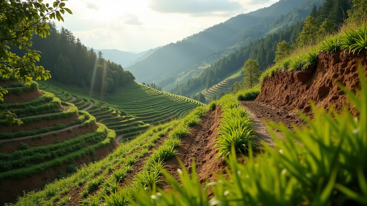
Converts a long, steep slope into a series of shorter, flatter slopes. Each terrace intercepts runoff, reduces velocity, and provides a level area where water infiltrates. Terracing has been used for at least 5,000 years across every continent.
Level terraces store water on the bench and allow it to infiltrate. Best in semi-arid regions where every drop matters.
Graded terraces carry water across the slope at a controlled velocity (typically 1–2 ft/s) to a stable outlet. Best in humid regions where infiltration capacity is regularly exceeded.
Broad-based terraces can be farmed across. The ridge and channel are gently sloped so equipment crosses without difficulty. Standard spacing: 100 to 150 feet of vertical interval, but site-specific design should account for soil type, rainfall intensity, and crop rotation.
Construction: use a laser level or transit to establish contour lines. Cut the bench to a minimum width of 6 feet (wider for equipment access). Compact the fill with a sheepsfoot roller or by repeated passes with a loaded scraper. Seed the backslope and channel immediately.
Contour Farming
The simplest structural modification: run all tillage, planting, and harvest operations on the contour rather than up and down slope. Each furrow becomes a small dam that intercepts runoff. On slopes up to 8%, contour farming alone reduces erosion by 25–50% compared to up-and-down tillage.
Establish contour lines with a laser level, A-frame level, or water tube level. Flag the line and follow it with all operations. On irregular topography, establish a key contour line and use it as the guide row, bending other rows to follow.
Check Dams
Small dams placed across gullies or drainage channels to reduce flow velocity and trap sediment. As sediment accumulates behind the dam, the gully floor rises, the slope flattens, and erosion force decreases.
Materials: rock (most durable), logs (5–10 year lifespan), woven wire filled with brush, sandbags (temporary), or manufactured products (excelsior logs, coir wattles).
Spacing rule: the top of each downstream dam should be level with the base of the next dam upstream. This creates a stairstep profile with a gentle gradient between dams. For a 10% slope in a 3-foot-deep gully, space 3-foot-high dams 30 feet apart.
Gabion Baskets
Wire mesh cages filled with rock. Used for check dams, retaining walls, streambank armoring, and channel lining. Gabions are flexible, they conform to ground movement without cracking. They also allow water to pass through, reducing hydrostatic pressure behind the structure.
Standard sizes: 3 ft x 3 ft x 6 ft or 3 ft x 3 ft x 9 ft. Use 11-gauge galvanized or PVC-coated wire mesh with 3-inch x 3-inch openings. Fill with hard, durable rock (4–8 inch diameter) that will not dissolve or weather rapidly. Limestone in acidic water is a poor choice. Granite, basalt, or hard sandstone works.
Wire together adjacent baskets with hog rings or lacing wire before filling. Place geotextile fabric behind gabions used as retaining walls to prevent soil piping through the rock fill.
Riprap
Loose stone placed on slopes or in channels to armor against erosion. The most common streambank and outlet protection method. Effective, durable, and straightforward.
Sizing depends on flow velocity. D50 (median stone diameter) for common applications: low velocity channels (under 4 ft/s): 4–6 inch stone. Moderate velocity (4–8 ft/s): 6–12 inch stone. High velocity (8–15 ft/s): 12–24 inch stone. Place on a layer of filter fabric or graded gravel filter to prevent soil migration through the riprap voids.
Thickness: minimum 1.5 times the D50 stone diameter or 12 inches, whichever is greater. Toe the riprap into the channel bottom or slope base by a minimum of 2 feet to prevent undermining.
Silt Fence
Temporary sediment barrier for construction sites and disturbed areas. Not a structural erosion control, it only traps sediment in sheet flow. It cannot handle concentrated flow, channel flow, or flow depths over 18 inches.
Installation: trench a 6-inch-deep slot along the contour. Set 36-inch wooden stakes at 6-foot spacing on the downslope side. Attach the fabric to the stakes and bury the bottom 6 inches in the trench, backfilling and compacting. The fabric should bow slightly toward the upslope side under load.
Common failures: installed across drainage channels (overwhelmed immediately), stakes placed upslope of fabric (fabric pulls away under load), no burial of bottom edge (water flows underneath), silt fence placed on slopes exceeding 2:1 (not designed for this).
5. Water Management
Erosion is a water problem. Control where water goes and how fast it gets there, and you control erosion.
Diversion Berms
Earth ridges built across a slope to intercept sheet flow and redirect it to a stable outlet. Used above construction sites, above gullies, above streambanks. Anywhere you need to keep runoff from reaching an erodible area.
Design: minimum 18 inches high after compaction. Side slopes no steeper than 3:1 for mowed areas, 2:1 for unmowed. Grade the channel at 0.5–1% to move water without causing channel erosion. Line the channel with grass or erosion blanket. Discharge to a stable area, rock outlet, established grass waterway, or vegetated basin.
Swales on Contour
Shallow, broad channels dug on the contour to intercept and infiltrate runoff. Unlike diversion berms, swales are designed to hold water until it soaks in. They have no outlet. The berm on the downhill side (the spoil from excavation) is planted with deep-rooted trees or grass.
Dimensions vary by rainfall and soil type. A typical swale for a 10-acre drainage in a 30-inch rainfall zone: 3 feet deep, 8–12 feet wide at the top, with a 4-foot berm on the downslope side. In clay soils, make swales wider and shallower to increase infiltration surface area. In sandy soils, narrower and deeper is acceptable.
Swales transform surface runoff into subsurface moisture. Trees planted on the berm below the swale access this stored moisture throughout the dry season. This is the foundation of dryland agroforestry, capture winter and spring rain in swales, grow food-producing trees on the berms year-round.
French Drains
Gravel-filled trenches that intercept subsurface water and redirect it. Used where saturated soil on slopes causes slumping and mass movement, a different erosion mechanism than surface flow, but equally destructive.
Construction: dig a trench 12–24 inches wide and 18–36 inches deep along the upslope edge of the problem area. Line with filter fabric, leaving excess to wrap over the top. Lay 4-inch perforated pipe in the bottom (holes down on flat ground, holes down in a French drain despite the common myth). Fill with clean, washed gravel (3/4 to 1.5 inch). Fold the excess fabric over the top. Cover with 4–6 inches of topsoil and seed.
Grade the pipe at a minimum 1% slope to a daylight outlet (a point where the pipe emerges on a lower slope and discharges to a stable area). Use solid (non-perforated) pipe for the last 10 feet before the outlet to prevent saturation at the discharge point.
Road and Trail Drainage
Roads concentrate and accelerate runoff. An unpaved road acts as a long, smooth channel, the worst possible geometry for erosion. Every road needs drainage features at close intervals.
Water bars: angled berms across a trail or road that divert water to the downhill side. Space at 50-foot intervals on 5% grades, 30-foot intervals on 10% grades, 20-foot intervals on 15%+ grades. Angle at 30–45 degrees to the road centerline. Build with a compacted soil berm 6–8 inches high, armored with rock on the outfall side.
Rolling dips: broad, gentle dips in the road surface that redirect water without creating a bump that damages vehicles. Better than water bars for roads with regular traffic. Construct with a 10–20 foot approach ramp, a shallow dip (4–6 inches below grade), and a rock-armored outlet on the downhill side.
Outsloping: tilting the entire road surface 3–5% toward the downhill edge so water sheets off continuously rather than concentrating. Only appropriate on roads with grades under 6% and non-erodible sideslopes. Above 6% grade, insloping with a ditch and cross-drains is safer.
Cross-drain culverts: buried pipes that carry ditch water under the road to the downhill side. Size for the 25-year storm at minimum. Space at the same intervals as water bars. Armor both inlet and outlet with riprap extending 2 diameters upstream and 4 diameters downstream.
6. Mulching
Mulch is the fastest erosion control you can deploy. It intercepts rainfall energy, reduces splash detachment by 90%+, slows surface flow, and maintains soil moisture for seed germination. Apply it the same day soil is exposed.
Organic Mulch Types
Straw: most common and cheapest. Apply at 2 tons per acre (roughly 1 bale per 800 square feet, 2–3 inches deep). Anchor on slopes with a mulch crimper, tackifier spray, or erosion netting. Avoid hay, it contains weed seed. Certified weed-free straw costs more but eliminates a future problem.
Wood chips: longer lasting than straw (1–3 years vs. 3–6 months). Apply 3–4 inches deep. Excellent for paths, orchard floors, and permanent mulched areas. Arborist chips (mixed species, leaves included) break down into excellent organic matter. Avoid dyed chips, the dyes add nothing and some contain contaminants.
Compost: a 2-inch layer of compost applied to a bare slope reduces erosion 80–95% while simultaneously feeding soil biology and providing a seedbed for grass establishment. This is the premium option. Expensive but produces the best long-term results. Composted materials filter stormwater pollutants as a side benefit.
Pine needles (pine straw): interlock naturally and resist displacement by wind and water better than straw. Apply 3–4 inches. Ideal for slopes under trees. Slightly acidifying, beneficial for blueberries, azaleas, and other acid-loving plants; neutral to slightly negative for others.
Geotextile Fabrics
Woven or non-woven synthetic fabrics placed on the soil surface. Two categories serve erosion control:
Filter fabrics (geotextiles): placed beneath rock, gravel, or soil to prevent fine particles from migrating through. They do not prevent erosion on their own. They prevent structural failure in armored systems. Use behind gabions, beneath riprap, around French drain gravel.
Weed barrier fabrics: sometimes misused for erosion control. They shed water rather than allowing infiltration, can increase runoff velocity downslope of the fabric, and degrade under UV exposure within 2–5 years. Not appropriate for erosion control except in narrow, specific applications (beneath gravel walkways, under riprap in channel bottoms).
Erosion Control Blankets (ECBs)
Manufactured rolls of organic or synthetic fiber designed to protect soil and promote vegetation establishment. Categories:
Single-net straw blankets: straw stitched between a light polypropylene net on top. Biodegrades in 6–12 months. Appropriate for mild slopes (3:1 or flatter) with low-velocity sheet flow. Cheapest option.
Double-net straw or coconut fiber blankets: fiber stitched between two nets. More durable, handles steeper slopes (2:1) and moderate flow. Coconut fiber (coir) lasts 2–5 years. Use where vegetation establishment is slow.
Turf reinforcement mats (TRMs): permanent synthetic matrix that vegetation grows through. Handles channel velocities up to 15–20 ft/s once fully vegetated. Used in grass waterways, channel linings, and steep slope stabilization where long-term performance is critical.
Installation: prepare the seedbed, apply seed and fertilizer, then unroll the blanket starting at the top of the slope. Anchor the top edge in a 6-inch-deep trench, staple at 3-foot intervals across the face, and overlap adjacent rolls by 4 inches minimum. On channels, start at the downstream end and work upstream so overlaps shed water.
Hydroseeding
Slurry of seed, mulch fiber, tackifier (binding agent), fertilizer, and water sprayed onto bare soil from a tank truck. Covers large areas fast. Standard mix: 50 lb seed, 2,000 lb wood fiber mulch, 50 lb tackifier, and 400 lb fertilizer per acre, delivered in 2,000+ gallons of water.
Advantages: fast application (an acre in under an hour), good seed-to-soil contact, consistent coverage, can reach slopes inaccessible to equipment.
Limitations: poor performance in extreme heat (slurry dries before seed germinates), thin application provides less erosion protection than straw mulch until germination occurs, requires specialized equipment.
Best practice: on critical slopes, hydroseed first, then apply straw mulch over the hydroseeded surface. The straw provides immediate erosion protection. The hydroseeded slurry provides seed and fertility beneath. This combination outperforms either method alone.
7. Streambank Stabilization
Streambank erosion is a different problem than upland erosion. The forces involved, channel flow velocity, wave action, ice scour, toe undermining, require methods that resist lateral hydraulic force, not just raindrop impact.
Soil Bioengineering Principles
The core concept: use living plant material as the primary structural element. Roots bind soil. Stems deflect flow. Canopy intercepts rainfall. As the plant grows, the structure strengthens. Every other material degrades.
Live Stakes
Dormant hardwood cuttings (willow, dogwood, cottonwood, sycamore) driven directly into the streambank. Cut 2–4 foot lengths from live branches, 1–2 inches in diameter. Sharpen the butt end. Drive at 2–3 foot spacing in a triangular pattern covering the bank from waterline to top. Insert at a slight downstream angle (10–15 degrees from vertical).
Timing: install during dormancy (late fall through early spring before bud break). Willows root the most aggressively, 80–90% success rate in moist soils. Keep stakes moist from cutting to installation. A 5-gallon bucket of water in the truck bed keeps cut stakes alive.
Fascines (Live Wattle)
Bundles of live willow or dogwood branches, 6–8 inches in diameter and 10–20 feet long, installed in shallow trenches on the streambank contour. The bundle is staked in place with dead stakes and partially buried. The stems root and sprout, creating a living erosion barrier.
Installation: dig a trench 6–8 inches deep on the contour. Lay the fascine in the trench. Drive 24-inch dead stakes through the bundle at 3-foot intervals. Backfill the downhill side with soil, leaving the top of the bundle exposed. Water heavily if conditions are dry.
Stack fascines at 3–5 foot vertical intervals on high banks. Combine with live stakes between the fascine rows for complete bank coverage.
Coir Logs
Manufactured logs of compressed coconut fiber wrapped in coir netting, 12–20 inches in diameter. Placed at the toe of streambanks to absorb wave energy and protect against undercutting while vegetation establishes above.
Installation: excavate a shallow trench at the waterline. Place the coir log in the trench and stake with 3-foot hardwood stakes or rebar at 3-foot intervals. Drive stakes through the log and 18 inches into the soil below. Plant live stakes through and above the coir log.
Lifespan: 2–5 years depending on submersion time and UV exposure. By the time the coir degrades, the live stakes planted through it should have established a root network that assumes the structural role. This is the design intent, temporary structure supporting permanent biology.
Root Wads
Harvested tree stumps with root mass intact, placed at the toe of eroding streambanks. The root fan faces upstream, deflecting current away from the bank. Effective for redirecting flow on outside meander bends where velocities are highest.
Installation requires heavy equipment. Excavate a pocket in the bank toe. Set the root wad with the trunk anchored into the bank at a 20–30 degree angle upstream. Backfill behind the root mass with clean gravel and topsoil. Cable to a buried deadman anchor (a log buried 6+ feet into the bank) for additional security.
Root wads look natural, provide aquatic habitat (the root mass creates pools and cover for fish), and resist substantial flow forces when properly anchored. They are expensive to install but permanent.
A-Frame Deflectors
Log or rock structures built in the stream channel to redirect flow away from eroding banks. Two logs or rock wings angle upstream from the bank, meeting at a point in the channel. Flow is deflected toward the center of the stream and away from the eroding bank.
These are in-stream structures and typically require permits from state and federal agencies (Army Corps of Engineers Section 404, state stream alteration permits). Consult with local NRCS or conservation district staff before constructing in-stream structures.
8. Keyline Design
P.A. Yeomans developed the Keyline system in Australia in the 1950s. It remains the most comprehensive landscape-scale water harvesting method available. The core insight: topography determines where water concentrates, and you can use that knowledge to spread it across the landscape rather than letting it accumulate in valleys and erode.
The Keypoint and Keyline
Every valley has a point where the slope transitions from steep (upper valley) to gentle (lower valley). This is the keypoint. The contour line that passes through the keypoint is the keyline. Above the keyline, water is concentrating. Below the keyline, it is spreading.
Yeomans' system maps the keypoint of every valley on the property and uses it as the reference for all subsequent development, roads, dams, fence lines, tree lines, and cultivation patterns.
Keyline Plow (Yeomans Plow)
A specialized subsoil plow that cuts a narrow slit 12–18 inches deep without inverting the soil. Unlike a moldboard plow that turns soil over (destroying structure and exposing organic matter to oxidation), the Keyline plow shatters compaction and creates infiltration channels while leaving the surface intact.
The critical technique: plow parallel to the keyline, but with a slight bias, lines drift gradually from valleys toward ridges. This means water that would normally flow down the valley is intercepted by the plow grooves and directed laterally toward the drier ridges. The valley gets drier (less erosion). The ridge gets wetter (more growth). Water is redistributed from where it concentrates to where it is scarce.
Run the Keyline plow annually in fall or early spring. Each pass deepens the infiltration channels and builds soil structure. Yeomans documented a 400% increase in topsoil depth over 3 years at his Yobarnie property, from 2 inches to 8+ inches, measured by the depth of dark, biologically active soil.
Keyline Water Harvesting
The system integrates dams at keypoints to capture excess runoff. These are not large reservoir dams. They are small (typically 1–5 acre-feet), shallow impoundments that store water at the highest practical elevation on the property. Gravity feeds this water through the landscape via contour channels, irrigation lines, or the Keyline plow grooves themselves.
The hierarchy of development in Yeomans' system: (1) climate, (2) landshape (topography), (3) water supply, (4) roads, (5) trees, (6) permanent buildings, (7) subdivision fences, (8) soil. Each level informs the next. The system is designed from the top of the watershed down, catching water at the highest point and using it at every level below.
Integration with Erosion Control
Keyline design is the strategic framework. The vegetative and structural methods described in sections 3 through 7 are tactical tools deployed within the Keyline framework. Swales on contour are Keyline features. Buffer strips follow Keyline patterns. Tree rows are planted on Keylines. The system unifies all erosion control methods into a coherent whole based on the actual shape of the land.
9. Construction Site Erosion
Construction sites are the most intense erosion sources in any watershed. Stripping vegetation, grading slopes, and compacting soil with heavy equipment creates conditions where erosion rates reach 1,000 times the pre-construction rate. Federal, state, and local regulations require specific controls.
SWPPP Requirements
A Stormwater Pollution Prevention Plan (SWPPP) is required by the EPA for any construction activity that disturbs one acre or more. Many states require it for smaller sites. The SWPPP must:
- Identify all potential pollutant sources (sediment, concrete washout, fuel, paint, etc.)
- Describe the BMPs (Best Management Practices) that will control each pollutant source
- Include a site map showing drainage patterns, BMP locations, and receiving waters
- Establish an inspection schedule (minimum every 7 days and within 24 hours of any 0.5-inch or greater rainfall)
- Document all inspections, maintenance, and corrective actions
The SWPPP is a living document, it changes as site conditions change. Failure to maintain a current SWPPP or implement its BMPs carries penalties up to $25,000 per day per violation under the Clean Water Act.
BMP Selection
Perimeter controls: silt fence around the downslope perimeter of all disturbed areas. Inlet protection (filter fabric, rock, or manufactured devices) around every storm drain inlet. Construction entrance stabilization (6 inches of 2–3 inch stone, 50 feet long, 20 feet wide minimum) to prevent tracking sediment onto public roads.
Sediment basins: required for drainage areas over 10 acres on most sites. Design to capture runoff from the 2-year, 24-hour storm. Provide a minimum 3,600 cubic feet of storage per acre of drainage. Include a skimmer or perforated riser for dewatering.
Slope stabilization: apply temporary seed and mulch within 14 days on any slope that will remain bare for more than 14 days. On slopes 3:1 or steeper, apply erosion control blankets over seed. Divert upslope clean water around disturbed areas with diversion berms.
Temporary vs. Permanent Measures
Temporary measures protect the site during construction. They are designed to be removed when permanent stabilization is achieved. Silt fence, construction entrance stone, temporary seeding, and temporary diversion berms fall in this category.
Permanent measures become part of the finished site. Permanent seeding, sod, riprap outlet protection, storm drain systems, detention ponds, and permanent retaining walls. The SWPPP must specify when each temporary BMP is replaced by a permanent one.
The transition is critical. Many erosion failures occur during the gap between removing temporary controls and establishing permanent ones. Maintain temporary BMPs until permanent vegetation reaches 70% density across the entire disturbed area. Do not remove silt fence until the area upslope is fully stabilized. Do not remove inlet protection until contributing areas are paved or vegetated.
Inspection and Maintenance
Every BMP fails without maintenance. Silt fence fills with sediment and overflows, remove accumulated sediment when it reaches one-third the fence height. Erosion blankets detach at staple points, re-staple and repair gaps immediately. Sediment basins lose capacity as sediment accumulates, clean out when storage volume drops below 50% of design capacity.
Inspect: every 7 calendar days, within 24 hours after any rainfall event of 0.5 inches or more, and before any predicted major storm. Document every inspection with photos, a site map of BMP conditions, and a corrective action log for any deficiencies found.
10. Sources
- Balcomb, J. Douglas. Passive Solar Buildings. MIT Press, 1992.
- EPA. "Stormwater Phase II Final Rule." EPA 833-F-00-008. 2005.
- Fiener, P. and K. Auerswald. "Effectiveness of grassed waterways in reducing runoff and sediment delivery from agricultural watersheds." Catena 52(1): 1–19. 2003.
- Gray, Donald H. and Robbin B. Sotir. Biotechnical and Soil Bioengineering Slope Stabilization. John Wiley & Sons, 1996.
- Helmers, M.J. et al. "Sediment removal by prairie filter strips in row-cropped ephemeral watersheds." Journal of Soil and Water Conservation 67(5): 354–360. 2012.
- Houben, Hugo and Hubert Guillaud. Earth Construction: A Comprehensive Guide. CRATerre-EAG, 1994.
- Kaspar, T.C. et al. "Rye cover crop and gamagrass strip effects on NO3 concentration and load in tile drainage." Soil Science Society of America Journal 65(5): 1434–1440. 2001.
- Lancaster, Brad. Rainwater Harvesting for Drylands and Beyond, Volume 2. Rainsource Press, 2008.
- Montgomery, David R. Dirt: The Erosion of Civilizations. University of California Press, 2007.
- USDA Agricultural Research Service. Revised Universal Soil Loss Equation Version 2 (RUSLE2). 2013.
- USDA NRCS. National Resources Inventory. 2017.
- Wischmeier, W.H. and D.D. Smith. Predicting Rainfall Erosion Losses: A Guide to Conservation Planning. USDA Agriculture Handbook 537. 1978.
- Yeomans, P.A. The Keyline Plan. Self-published, 1954.
- Yeomans, P.A. Water for Every Farm. Keyline Designs, 1965.
Research on erosion control
Peer reviewed studies about erosion control, listed so you can read the original rather than take our word for it. They are background on the subject, not a source for any one sentence above.
- Assessing the soil erosion control service of ecosystems change in the Loess Plateau of China (2011). doi:10.1016/j.ecocom.2011.07.003
- Landslide erosion controlled by hillslope material (2010). doi:10.1038/ngeo776
- Erosional control of active compressional orogens (1992). doi:10.1007/978-94-011-3066-0_1
- Biotechnical and soil bioengineering slope stabilization: a practical guide for erosion control (1997). doi:10.5860/choice.34-3327
- The role of fine and coarse roots in shallow slope stability and soil erosion control with a focus on root system architecture: a review (2007). doi:10.1007/s00468-007-0132-4
- Debris flow and erosion control problems caused by the ash eruptions of Irazu Volcano, Costa Rica (1967). doi:10.3133/b1241i
- Bioengineering for Streambank Erosion Control. Report 1 - Guidelines. (1997). doi:10.21236/ada326294
- Tree-compatible ground covers for reforestation and erosion control (2009). read the study
- Soil erosion control after wildfire (2019). read the study
Common questions
What are vegetative methods?
Living plants are the most effective, most durable, and cheapest erosion control available. A field with 60% ground cover reduces erosion by approximately 90% compared to bare soil. At 90% cover, erosion effectively stops under all but the most extreme conditions. The fastest vegetative stabilization for agricultural land. Broadcast seed into standing crops before harvest or drill immediately after harvest.
What are structural methods?
Use structural methods where water forces exceed what vegetation alone can resist, where slopes are too steep for planting, or where you need immediate erosion arrest while vegetation establishes. Converts a long, steep slope into a series of shorter, flatter slopes. Each terrace intercepts runoff, reduces velocity, and provides a level area where water infiltrates. Terracing has been used for at least 5,000 years across every continent. Level terraces store water on the bench and allow it to infiltrate.
What is water management?
Erosion is a water problem. Control where water goes and how fast it gets there, and you control erosion. Earth ridges built across a slope to intercept sheet flow and redirect it to a stable outlet. Used above construction sites, above gullies, above streambanks. Anywhere you need to keep runoff from reaching an erodible area.
What is streambank stabilization?
Streambank erosion is a different problem than upland erosion. The forces involved, channel flow velocity, wave action, ice scour, toe undermining, require methods that resist lateral hydraulic force, not just raindrop impact. Soil Bioengineering Principles. The core concept: use living plant material as the primary structural element. Canopy intercepts rainfall.
What is keyline design?
Yeomans developed the Keyline system in Australia in the 1950s. It remains the most comprehensive landscape-scale water harvesting method available. The core insight: topography determines where water concentrates, and you can use that knowledge to spread it across the landscape rather than letting it accumulate in valleys and erode. The Keypoint and Keyline. Every valley has a point where the slope transitions from steep (upper valley) to gentle (lower valley).
What is construction site erosion?
Construction sites are the most intense erosion sources in any watershed. Stripping vegetation, grading slopes, and compacting soil with heavy equipment creates conditions where erosion rates reach 1,000 times the pre-construction rate. Federal, state, and local regulations require specific controls. A Stormwater Pollution Prevention Plan (SWPPP) is required by the EPA for any construction activity that disturbs one acre or more. Many states require it for smaller sites.