science
Hydraulic Systems
A comprehensive guide covering Hydraulic Systems.
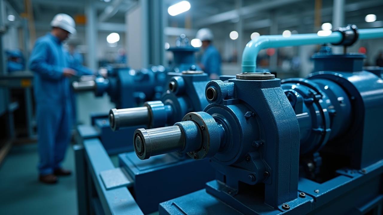
1. Introduction — Pascal's Law and Force Multiplication
Blaise Pascal figured it out in 1653. Pressure applied to a confined fluid transmits equally and undiminished in all directions. He published it posthumously in 1663 in Traité de l'Équilibre des Liqueurs. That single principle underpins every hydraulic brake, every excavator arm, every aircraft flight control surface, and every shop press in existence.
The math is direct. Pressure equals force divided by area (P = F/A). If you apply 10 pounds of force to a piston with 1 square inch of area, you create 10 PSI throughout the entire closed system. That same 10 PSI acting on a piston with 10 square inches of area produces 100 pounds of force. You multiplied force by a factor of 10. The trade-off: the small piston must travel 10 inches to move the large piston 1 inch. You never get free energy — you trade distance for force.
Joseph Bramah built the first practical hydraulic press in 1795, patented as the Bramah Press. It could exert forces that no mechanical linkage of its era could match. Industrial hydraulics matured through the early 1900s. Harry Vickers developed the first balanced vane pump in the 1920s. By World War II, hydraulic systems powered gun turrets, landing gear, and bomb bay doors. Post-war, hydraulics moved into construction equipment, manufacturing, and agriculture.
Modern hydraulic systems operate at pressures from 500 PSI (low-pressure utility circuits) to 10,000+ PSI (industrial presses and waterjet cutters). Mobile equipment — excavators, skid steers, tractors — typically runs 2,500-4,000 PSI. The power density is unmatched: a hydraulic motor the size of a coffee can produces the same torque as an electric motor the size of a trash barrel.
Three reasons hydraulics dominate heavy work. First, force multiplication through area ratios — no gearbox needed. Second, flexible power routing — steel tubing and hose can route force around corners, through walls, and across distances that rigid mechanical linkages cannot. Third, infinitely variable speed control through flow regulation. A single pump can power multiple actuators doing different things at different speeds simultaneously.
This document covers the core knowledge needed to design, build, maintain, and troubleshoot hydraulic systems from shop-scale to mid-size mobile equipment.
2. Components — What Every System Contains
Every hydraulic system, from a bottle jack to a mining excavator, contains the same functional categories of components.
Reservoir (tank). Stores fluid, allows air separation and heat dissipation, provides suction head to the pump. Minimum reservoir size: 2-3 times pump GPM for mobile systems, 3-5 times pump GPM for industrial. Baffled internally to separate return flow from suction, giving air bubbles time to rise and escape. Includes fill/breather cap, sight gauge or level sensor, drain plug, and suction strainer.
Pump. Converts mechanical energy (electric motor, engine PTO, hand lever) into hydraulic flow. The pump does not create pressure — it creates flow. Pressure results from resistance to that flow downstream. Critical ratings: gallons per minute (GPM) determines actuator speed, maximum PSI determines system force capability.
Control valves. Direct, regulate, and limit fluid flow and pressure. Three categories: directional (route flow to different actuators), pressure (limit or reduce system pressure), and flow (control actuator speed). Detailed in Section 6.
Actuators. Convert hydraulic pressure back into mechanical force and motion. Two types: cylinders (linear motion) and motors (rotary motion). Detailed in Section 5.
Filters. Remove particulate contamination from fluid. Minimum: suction strainer (100-150 mesh), return line filter (10-25 micron), and breather filter on reservoir. Servo and proportional valve systems need 3-5 micron filtration with high beta ratios.
Hoses and tubing. Route fluid between components. Rigid steel tubing for fixed runs. Flexible hose for connections to moving components. Rated by working pressure and burst pressure with a standard 4:1 safety factor (SAE J517). Detailed in Section 8.
Fittings and connectors. Join hoses, tubes, and components. JIC 37° flare, O-Ring Boss (ORB), and NPT pipe threads are the three dominant standards in North America. Mixing fitting types is a primary cause of leaks. Detailed in Section 8.
Heat exchangers. Dissipate waste heat. Hydraulic systems are inherently inefficient — 20-40% of input energy becomes heat. Air-cooled and water-cooled heat exchangers maintain fluid temperature below 180°F (82°C). Above that, fluid oxidation accelerates exponentially and seal life drops.
Accumulators. Store pressurized fluid for shock absorption, energy storage, and emergency power. Bladder, piston, and diaphragm types. Pre-charged with nitrogen — never use oxygen or compressed air (explosion risk).
3. Hydraulic Fluid — Viscosity, Types, and Contamination
Hydraulic fluid does four jobs: transmit force, lubricate moving parts, transfer heat away from components, and seal internal clearances. Selecting the wrong fluid or allowing it to degrade causes more system failures than any mechanical deficiency.
Viscosity Grades
Viscosity is measured in centistokes (cSt) at 40°C per ISO 3448. The ISO VG number equals the midpoint viscosity at 40°C.
| ISO VG Grade | Viscosity at 40°C (cSt) | Typical Application |
|---|---|---|
| VG 15 | 13.5-16.5 | Precision instruments, spindle hydraulics |
| VG 22 | 19.8-24.2 | Indoor machine tools, cold climate mobile |
| VG 32 | 28.8-35.2 | General industrial hydraulics, moderate climate mobile |
| VG 46 | 41.4-50.6 | Most common — mobile equipment, outdoor industrial |
| VG 68 | 61.2-74.8 | Hot climate, high-pressure systems, heavily loaded pumps |
| VG 100 | 90-110 | Extreme heat, large slow systems |
The operating window matters more than the grade. Every pump has a minimum and maximum viscosity tolerance — typically 10-1,000 cSt for gear pumps, 10-160 cSt for vane pumps, 10-400 cSt for piston pumps. Below minimum viscosity, internal leakage increases and lubrication fails. Above maximum viscosity, pump cavitates because oil cannot fill the inlet fast enough.
For most applications in temperate climates, VG 46 anti-wear hydraulic oil covers the range. Cold-start environments (below 20°F / -7°C) need VG 32 or multigrade fluids.
Mineral Oil vs. Synthetic
Mineral oil (petroleum-based). Covers 90%+ of hydraulic applications. Adequate performance, lowest cost ($15-$30 per gallon), compatible with standard seals (Buna-N, nitrile). Anti-wear additives (zinc dithiophosphate — ZDDP) protect pump internals. Change interval: 2,000-4,000 hours or annually, whichever comes first.
Synthetic (PAO, ester-based). Extended temperature range (-40°F to 250°F vs. mineral's 0°F to 200°F), better oxidation stability, longer life. Cost: $40-$100 per gallon. Justified in extreme temperature applications, systems with long drain intervals, or where fire resistance matters. Check seal compatibility — some synthetics attack standard nitrile seals and require Viton or PTFE.
Biodegradable (vegetable ester, HEES). Required in environmentally sensitive applications — forestry, marine, agriculture near waterways. Performance comparable to mineral oil in the short term but oxidizes faster. Change interval: 1,000-2,000 hours. Cost: $30-$60 per gallon.
Fire-resistant (water-glycol, phosphate ester). Used near open flame, molten metal, or furnaces. Water-glycol fluids require stainless steel or painted components (corrosive to zinc and cadmium). Phosphate ester fluids attack standard paint, seals, and hose linings — dedicated system components required.
Contamination — The Number One Killer
Pall Corporation's field data shows contamination causes 75-85% of hydraulic system failures. Three types of contamination destroy systems.
Particulate. Metal wear particles, seal fragments, dirt ingestion through breathers and worn rod seals. Particles as small as 5 microns (invisible to the eye) score valve spools, erode pump gear faces, and jam check valves. New oil from the barrel is not clean enough for most systems — it must be filtered during filling.
Water. Enters through breathers, worn seals, and condensation. Water in hydraulic oil causes corrosion, accelerates additive depletion, reduces lubricity, and creates vapor bubbles that implode and erode metal surfaces (cavitation). Maximum acceptable water content: 0.1% (1,000 ppm) for gear pump systems, 0.05% (500 ppm) for piston pump and servo valve systems.
Air. Entrained air makes fluid compressible, causing spongy operation and erratic actuator movement. Air bubbles passing through the pump collapse violently at the pressure side (aeration), eroding pump internals. Sources: low reservoir level, suction leaks, return line above fluid level, and foaming from water contamination.
Cleanliness standard: ISO 4406 rates fluid cleanliness with three numbers representing particle counts per milliliter at 4, 6, and 14 microns. Example: ISO 18/16/13. Lower numbers mean cleaner fluid. Target cleanliness depends on the most sensitive component in the circuit.
| Component | Target ISO Cleanliness |
|---|---|
| Gear pumps, cylinders | 20/18/15 |
| Vane pumps | 18/16/13 |
| Piston pumps | 17/15/12 |
| Proportional valves | 16/14/11 |
| Servo valves | 15/13/10 |
4. Pump Types — Gear, Vane, and Piston
The pump is the heart of the system. Selecting the wrong pump guarantees either insufficient performance or premature failure. Three main categories cover virtually all applications.
Gear Pumps
Two meshing gears inside a housing. Fluid enters on the expanding side (where teeth unmesh), gets carried around the outside in the pockets between gear teeth and housing, and is squeezed out on the contracting side (where teeth mesh).
External gear pumps. Two spur gears on parallel shafts. The most common hydraulic pump worldwide. Simple, cheap, tolerant of contamination, and field-rebuildable.
- Pressure range: up to 4,000 PSI (most rated 2,500-3,500 PSI)
- Flow range: 0.5-150 GPM
- Efficiency: 80-90% volumetric, 85-93% overall
- Cost: $150-$1,500 depending on size
- Limitations: Fixed displacement only. Noisy at high pressure. Efficiency drops as internal clearances wear.
Internal gear pumps (gerotor). One gear orbits inside a larger internal gear. Quieter than external gear. Common in machine tool hydraulics and automotive power steering.
- Pressure range: up to 3,000 PSI
- Flow range: 0.5-50 GPM
- Efficiency: 85-93% volumetric
- Lower noise, better for indoor use
Vane Pumps
A rotor with sliding vanes spins inside a cam ring. Vanes extend outward by centrifugal force and spring pressure, creating sealed chambers that expand on the inlet side and compress on the outlet side.
Fixed displacement. Cam ring is circular — output is constant at a given RPM.
Variable displacement. Cam ring position adjusts to change the eccentricity (offset) between rotor and ring. Maximum eccentricity = maximum flow. Zero eccentricity = zero flow. Pressure-compensated vane pumps reduce flow automatically as system pressure rises, reducing heat generation at stall.
- Pressure range: up to 3,000 PSI (most rated 1,500-2,500 PSI)
- Flow range: 1-80 GPM
- Efficiency: 90-95% volumetric
- Cost: $300-$2,500
- Best for: Indoor industrial systems where low noise and long life matter. Sensitive to contamination — requires 25 micron or finer filtration.
Piston Pumps
Pistons reciprocating in bores — the highest pressure and efficiency of any pump type.
Axial piston (swashplate). Pistons arranged in a circle parallel to the drive shaft. A tilting swashplate pushes pistons back and forth. Swashplate angle determines displacement — variable displacement by design. The standard for mobile equipment and high-pressure industrial.
- Pressure range: up to 6,000 PSI (some rated 10,000 PSI)
- Flow range: 1-250 GPM
- Efficiency: 92-98% volumetric, 88-95% overall
- Cost: $1,000-$15,000+
- Best for: Mobile equipment, high-pressure circuits, systems requiring variable displacement and pressure compensation.
Radial piston. Pistons arranged radially around an eccentric shaft. High torque at low speed. Used in heavy industrial presses, winches, and marine applications.
Fixed vs. Variable Displacement
Fixed displacement: Output volume per revolution is constant. System pressure builds until the relief valve opens, dumping excess flow as heat. Simple and cheap. Acceptable for intermittent-duty systems (log splitters, presses) where the pump runs under load only briefly.
Variable displacement: Output adjusts based on demand. Pressure-compensated pumps reduce displacement as system pressure approaches the compensation setting — no flow over the relief valve, minimal heat generation. Essential for continuous-duty systems. Higher cost justified by reduced energy waste and heat management.
Pump Sizing
Two numbers define pump sizing: GPM (flow rate) and PSI (pressure rating).
GPM determines speed. Cylinder speed (in/min) = (GPM × 231) ÷ cylinder area (in²). A 5 GPM pump extending a 3-inch bore cylinder: (5 × 231) ÷ 7.07 = 163 inches per minute, or about 13.6 feet per minute.
PSI determines force. Cylinder force (lbs) = PSI × piston area (in²). A 3-inch bore cylinder at 3,000 PSI: 3,000 × 7.07 = 21,206 lbs of push force.
Horsepower requirement: HP = (GPM × PSI) ÷ 1,714. A 10 GPM pump at 3,000 PSI: (10 × 3,000) ÷ 1,714 = 17.5 HP. Add 10-15% for pump inefficiency — 20 HP motor minimum.
5. Cylinders — Single-Acting, Double-Acting, and Sizing
Hydraulic cylinders convert pressure into linear force and motion. Two fundamental types.
Single-Acting Cylinders
Hydraulic pressure extends the cylinder. Retraction by gravity, spring, or external load. Simpler plumbing — one hose. Common in jacks, dump trailers, and lifts where gravity handles the return stroke.
Limitation: no powered retraction. If the load resists retraction or the cylinder is mounted horizontally, single-acting will not work.
Double-Acting Cylinders
Hydraulic pressure extends and retracts the cylinder. Two ports — one on each side of the piston. The standard for most applications.
Differential area effect. The rod side of the piston has less area than the cap side (the rod takes up space). A 4-inch bore cylinder with a 2-inch rod has: cap side area = 12.57 in², rod side area = 12.57 - 3.14 = 9.42 in². At 3,000 PSI: push force = 37,710 lbs, pull force = 28,274 lbs. Retraction is also faster than extension at the same flow rate because less volume is needed to fill the rod side.
Bore and Rod Sizing
Bore (cylinder diameter) determines force capacity. Select bore based on maximum required force divided by system pressure. Always include a 20-30% force margin for friction, back pressure, and load variations.
| Bore (in) | Piston Area (in²) | Force at 3,000 PSI (lbs) |
|---|---|---|
| 2.0 | 3.14 | 9,420 |
| 2.5 | 4.91 | 14,726 |
| 3.0 | 7.07 | 21,206 |
| 3.5 | 9.62 | 28,864 |
| 4.0 | 12.57 | 37,699 |
| 5.0 | 19.63 | 58,905 |
| 6.0 | 28.27 | 84,823 |
Rod diameter determines retract force capability and resistance to buckling under compression. Standard rod-to-bore ratios: 0.5 for moderate loads, 0.6-0.7 for heavy side loads or long stroke applications. For cylinders over 40 inches of stroke under compressive load, check Euler's column buckling formula or use manufacturer stop-tube and rod diameter recommendations.
Stroke is the total travel distance. Select based on the range of motion needed plus 0.5-1 inch of margin on each end. Cushions (deceleration chambers built into the cylinder ends) prevent slamming at end of stroke — specify cushioned ends for any cylinder operating at speed.
Mounting Styles
- Clevis (pin mount). Pivots on a pin at one or both ends. For applications where the cylinder must arc as it extends. Standard on loader arms, bucket tilts, and steering cylinders.
- Cross tube. Fixed mount through a tube welded to the cylinder cap. Common on agricultural equipment and log splitters.
- Flange mount. Bolted to a flat surface. For presses and industrial applications with straight-line loads.
- Trunnion. Side-mounted pivot pins on the cylinder barrel. For heavy-duty pivoting applications — crane booms, excavator sticks.
- Tie rod. Four external rods hold the end caps to the barrel. Standard NFPA interchange dimensions. Easy to disassemble and reseal. The most common industrial cylinder style.
6. Control Valves — Directional, Pressure, and Flow
Control valves are the decision-makers in a hydraulic circuit. They determine where fluid goes, how much pressure it reaches, and how fast actuators move.
Directional Control Valves
Route fluid to different actuator ports. Described by three characteristics: number of ports (ways), number of positions, and center condition.
Spool valves. A machined spool slides inside a bore, opening and closing flow paths. The dominant directional valve type.
- 4-way, 3-position (4/3). Four ports (P=pressure, T=tank, A and B=actuator ports), three spool positions (extend, neutral, retract). The standard for double-acting cylinders and reversible motors.
- 3-way, 2-position. Three ports, two positions. For single-acting cylinders — one position pressurizes, the other drains to tank.
Center conditions (what happens at neutral):
- Open center. All ports connected. Pump flow returns to tank at low pressure. Standard for fixed-displacement pump systems — prevents pressure buildup at idle.
- Closed center. All ports blocked. Holds actuator position under load. Requires a pressure-compensated pump or accumulator to manage flow at neutral.
- Tandem center. P and T connected (pump unloaded), A and B blocked (actuator held). Good compromise for fixed-displacement systems that need to hold loads at neutral.
- Float center. P blocked, T/A/B connected. Actuator free to move by external forces. Used for blade float on graders and dozers.
Actuation methods: Manual lever (most common on mobile), solenoid (electrical control), hydraulic pilot (for high-flow valves that need too much force for solenoids), pneumatic pilot.
Pressure Control Valves
Relief valve. Sets maximum system pressure. When pressure exceeds the setting, the valve opens and diverts flow to tank. Every hydraulic system must have a relief valve — it is the safety limit. Set 10-15% above maximum working pressure. Direct-acting for flows under 15 GPM; pilot-operated for higher flows (less pressure override, more stable).
Pressure reducing valve. Creates a lower-pressure sub-circuit within a higher-pressure system. Spring-closed, normally open. Used when one actuator in a multi-circuit system requires lower force than the main system provides. Example: a clamp cylinder at 800 PSI in a 3,000 PSI press circuit.
Sequence valve. Allows flow to a secondary circuit only after the primary circuit reaches a set pressure. Ensures operations happen in order — clamp closes before press advances.
Counterbalance valve. Prevents uncontrolled lowering of suspended loads. Creates back pressure on the rod side of a cylinder to prevent the load from outrunning the pump flow. Critical on crane booms, vertical lifts, and any cylinder holding weight.
Flow Control Valves
Needle valve. Variable orifice adjustable by hand. The simplest speed control — restrict flow to slow an actuator. Not pressure-compensated, so actuator speed changes with load variation.
Pressure-compensated flow control. Maintains constant flow regardless of pressure changes upstream or downstream. Contains a needle valve plus a hydrostat (pressure-compensating spool). Necessary for consistent speed under varying loads.
Flow divider. Splits one flow stream into two equal (or proportional) outputs. Used to synchronize two cylinders or divide pump flow between two circuits. Gear-type flow dividers maintain ratio within 3-5% accuracy.
7. Circuit Design — Basic, Regenerative, and Speed Control
Basic Cylinder Circuit
The minimum viable hydraulic circuit for a double-acting cylinder:
- Reservoir
- Pump (driven by motor or engine)
- Relief valve (on pump outlet, set to maximum system pressure)
- Directional control valve (4/3)
- Cylinder
- Return filter (on tank return line)
Flow path: Reservoir → pump → relief valve (tee) → directional valve → cylinder (A or B port) → directional valve → return filter → reservoir.
The relief valve must be plumbed as a tee off the pressure line, not in series. At neutral (open center), pump flow passes through the directional valve back to tank at minimal pressure. When the spool shifts, flow goes to the cylinder. If the cylinder stalls against a load, pressure rises until the relief valve opens, protecting the pump and circuit from overpressure.
Regenerative Circuit
Speeds up cylinder extension by routing rod-side return oil to the cap side instead of back to tank. During extension, both pump flow and rod-side displaced fluid feed the cap side. Result: faster extension at reduced force.
Speed increase factor = bore area ÷ (bore area - rod area). With a 4-inch bore and 2-inch rod: 12.57 ÷ (12.57 - 3.14) = 1.33x faster extension than standard circuit.
Force reduction: only the rod area produces net force in regen mode (cap side pressure acts on both sides, canceling out over the shared area). Force = PSI × rod area instead of PSI × bore area.
Regen circuits are standard on press rapid-approach stages — fast travel at low force to close the gap, then switch to standard circuit for full-force pressing.
Speed Control — Meter-In vs. Meter-Out
Meter-in. Flow control valve on the inlet side of the actuator. Restricts flow entering the cylinder to control extension/retraction speed. Excess pump flow goes over the relief valve (wasteful with fixed-displacement pumps). Best for: resistive loads — loads that oppose the direction of motion (pushing against a press force).
Meter-out. Flow control valve on the outlet side of the actuator. Restricts flow leaving the cylinder. Creates back pressure that controls speed. Best for: overrunning loads — loads that try to move faster than the pump can fill the cylinder (lowering a heavy weight). Meter-out prevents the load from running away by maintaining controlled back pressure.
Rule of thumb: If the load could pull the cylinder faster than the pump fills it, use meter-out. If the load always resists cylinder motion, either method works, but meter-in is slightly more energy-efficient.
Bleed-off (bypass). Diverts a portion of pump flow to tank before it reaches the actuator. The actuator gets whatever flow remains. Most energy-efficient method with fixed-displacement pumps — no flow over the relief valve. Least precise speed control. Suitable for rough speed adjustment only.
8. Hose and Fitting Selection
Hose and fitting failure causes the majority of hydraulic fluid spills and is a leading cause of hydraulic fires on mobile equipment. Proper selection prevents both.
Hose Pressure Ratings
Hydraulic hose is rated by working pressure with a 4:1 burst-to-working pressure safety factor per SAE J517. Never exceed working pressure — the burst rating is not a safe operating zone. It is the point of catastrophic failure.
| SAE Hose Type | Construction | Working Pressure (PSI) | Typical Use |
|---|---|---|---|
| 100R1 (1SN) | 1 wire braid | 1,450-3,250 (varies by size) | Medium pressure, general hydraulics |
| 100R2 (2SN) | 2 wire braid | 2,175-5,800 | High pressure, most mobile equipment |
| 100R12 | 4 spiral wire | 4,000-5,000 | Very high pressure, excavators, presses |
| 100R13 | 4/6 spiral wire | 5,000-6,000 | Extreme pressure, heavy construction |
| 100R15 | 4/6 spiral wire | 5,000-6,000 | Impulse-resistant, long flex life |
Hose Sizing by Flow Velocity
Undersized hose creates excessive velocity, causing turbulent flow, heat generation, and pressure drop. Oversized hose wastes money and adds weight.
Velocity guidelines (industry standard):
- Pressure lines: 15-20 ft/sec maximum
- Return lines: 10-15 ft/sec maximum
- Suction lines: 2-4 ft/sec maximum (critical — too fast causes pump cavitation)
Formula: Velocity (ft/sec) = (0.3208 × GPM) ÷ internal area (in²)
| Flow (GPM) | Min Hose ID for Pressure (in) | Min Hose ID for Return (in) | Min Hose ID for Suction (in) |
|---|---|---|---|
| 5 | 3/8 (0.375) | 1/2 (0.500) | 3/4 (0.750) |
| 10 | 1/2 (0.500) | 5/8 (0.625) | 1.0 |
| 15 | 5/8 (0.625) | 3/4 (0.750) | 1.25 |
| 20 | 3/4 (0.750) | 1.0 | 1.50 |
| 30 | 1.0 | 1.25 | 2.0 |
Fitting Types
JIC 37° flare (SAE J514). The most common hydraulic fitting in North America. Metal-to-metal seal on a 37° flare cone. Reusable — can be disassembled and reassembled multiple times. Reliable to 6,000+ PSI. The default choice for most applications.
O-Ring Boss (ORB, SAE J1926). Straight thread with an O-ring that seals against a machined flat seat. More reliable than JIC in vibration environments — the O-ring provides a positive seal independent of torque. Standard on most OEM equipment manifolds and valve bodies.
NPT (National Pipe Thread). Tapered thread that seals by thread deformation and pipe sealant (PTFE tape or anaerobic sealant). The oldest fitting standard and the least reliable in hydraulic applications. Prone to leaks from vibration loosening, thread galling, and inconsistent taper engagement. Use only where component ports require it — never as the primary connection standard for new system design.
BSPP (British Standard Pipe Parallel). Parallel thread with a bonded seal or washer. Common on European and Asian equipment. Not interchangeable with NPT despite similar appearance — cross-threading destroys both fittings.
Rule: Never mix fitting standards in a circuit. Pick one standard (JIC or ORB) and adapt everything to it. Every adapter is a potential leak point. Every transition between standards introduces a failure mode that pure JIC or pure ORB circuits do not have.
9. Troubleshooting — Symptoms, Causes, and Diagnosis
Slow Operation
The actuator moves but slower than normal.
Check first: Fluid level in reservoir. Low level means the pump may be cavitating (drawing air instead of oil on partial strokes).
Common causes:
- Worn pump — internal leakage increases with wear, reducing effective flow. Test: install a flow meter on the pump outlet. Compare actual GPM to rated GPM at operating pressure. Below 80% of rated flow = pump rebuild or replace.
- Partially blocked filter — increased back pressure on the return line robs energy. Check filter indicator. Replace if differential pressure exceeds manufacturer specification.
- Fluid viscosity too high — cold oil moves slowly through orifices and valve passages. Check fluid temperature. Systems should reach 100-130°F (38-54°C) operating temperature within 10-15 minutes of operation.
- Internal cylinder bypass — worn piston seal leaks fluid past the piston. Test: fully extend the cylinder against a stop, disconnect the rod-side hose. Oil flowing from the disconnected port = piston seal failure.
- Relief valve set too low or partially open — diverting flow to tank before reaching the actuator. Check relief valve setting with a calibrated pressure gauge.
Overheating
Fluid temperature consistently above 180°F (82°C).
Common causes:
- Relief valve is primary suspect. If the system spends significant time at relief (stalling against loads, oversized pump for the application), all that flow is converted directly to heat.
- Undersized reservoir — insufficient heat dissipation area. Add an air-cooled heat exchanger if reservoir size cannot be increased.
- Fluid viscosity too low for operating temperature — internal leakage across every clearance in the system generates heat. Check fluid grade against operating temperature.
- Blocked cooler fins — clean with compressed air or pressure washer.
- Aeration — entrained air compresses and generates heat. Check for suction leaks, low fluid level, and return line above fluid level.
Leaks
External leaks. Visible at fittings, hose connections, cylinder rod seals, and valve bodies.
- Fittings: re-torque JIC fittings per SAE specifications. Replace O-rings on ORB fittings. Replace NPT fittings and re-apply thread sealant.
- Cylinder rod seals: replace entire seal kit, not individual seals. Inspect rod surface for scoring — a scored rod destroys new seals within hours.
- Hose: replace the entire hose assembly. Never patch or splice hydraulic hose.
Internal leaks. Not visible but cause slow operation, heat generation, and loss of holding force. Fluid bypasses from high-pressure to low-pressure side across worn seals and clearances. Diagnosed by isolation testing — disconnect actuator ports and measure leakage flow at system pressure.
Cavitation
Audible as a high-pitched whine or rattle from the pump. Caused by incomplete filling of pump chambers — vapor bubbles form in low-pressure zones and collapse violently at the high-pressure side.
Causes: Restricted suction line (clogged strainer, undersized suction hose, suction line too long or too many fittings), cold oil too viscous to flow, reservoir mounted below pump with insufficient suction head, suction fitting air leak.
Diagnosis: Install a vacuum gauge on the pump inlet. Reading should not exceed 5 inches of mercury (5 inHg) vacuum. Above 5 inHg indicates suction restriction.
Damage: Cavitation erodes pump internals rapidly. A cavitating pump can be destroyed in 100-200 hours of operation. The whine is not just noise — it is the sound of metal being removed from pump surfaces by collapsing vapor bubbles.
Aeration
Similar symptoms to cavitation but caused by air entering the system rather than vapor formation. Spongy actuator response, foamy fluid in reservoir, erratic operation.
Sources: Low fluid level exposing suction port, suction line air leak (check fittings and hose connections above fluid level), return line discharge above fluid level creating turbulence and air entrainment, worn shaft seal on pump allowing air ingestion.
Test: Inspect fluid through the reservoir sight glass during operation. Foamy or cloudy fluid indicates aeration. Healthy fluid is clear and bubble-free.
Noise
Pump whine (high pitch): Cavitation or aeration. Address suction restrictions.
Pump knock (rhythmic): Worn bearings or loose coupling. Shut down and inspect before catastrophic failure.
Relief valve chatter: Worn relief valve seat or setting too close to operating pressure. Rebuild or replace relief valve.
Water hammer (sharp bang on valve shift): Excessive actuator speed, no deceleration. Add cushions to cylinders, install deceleration valves, or reduce shifting speed on directional valves.
10. Maintenance — Fluid Analysis, Filters, and Inspection
Fluid Sampling and Analysis
Fluid analysis is the most cost-effective predictive maintenance tool for hydraulic systems. A $25-$40 lab analysis catches developing problems months before they cause component failure.
Sampling frequency: Every 500 hours for mobile equipment, every 1,000 hours for industrial systems, and immediately after any component failure.
Sampling method: Take samples from a live, warm system through a designated sample port or valve — never from the drain plug or the fill cap. Use clean sample bottles from the lab. The sample must represent circulating fluid, not settled contaminants.
What the lab reports:
- Particle count (ISO 4406). Current contamination level. Compare to target cleanliness for your most sensitive component.
- Viscosity at 40°C. If more than 10% above or below the new-oil specification, the fluid is degraded or contaminated. High viscosity: oxidation or wrong fluid added. Low viscosity: thermal breakdown, fuel dilution, or wrong fluid added.
- Water content (Karl Fischer). Above 0.1% = investigate source. Above 0.5% = change fluid immediately and repair the ingression point.
- Acid number (TAN). Measures oxidation and additive depletion. Rising TAN means the fluid is acidifying. Above 2.0 mg KOH/g: replace the fluid.
- Wear metals (ICP spectroscopy). Iron = gear and bearing wear. Copper = bushing and thrust plate wear. Chrome = cylinder rod or piston ring wear. Silicon = dirt ingestion. Trending these values over multiple samples reveals developing failures.
Filter Replacement
Replace filters based on condition, not calendar. Most hydraulic filters have a differential pressure indicator — a pop-up button or gauge showing pressure drop across the element. When differential pressure reaches the indicator setting (typically 25-30 PSI for return filters), the element is loaded. Continued operation past indicator trips the bypass valve, allowing unfiltered oil through the system.
Filter replacement procedure:
- Relieve system pressure. Open a bleed valve or cycle the directional valve with the pump off to release stored energy.
- Place an absorbent pad under the filter housing.
- Remove the housing or spin-on canister. Inspect the used element for metal particles — large particles indicate component failure upstream.
- Clean the housing interior before installing the new element.
- Install new element with new O-rings (pre-lubricate O-rings with clean hydraulic oil).
- Fill the housing with clean fluid before closing to minimize air entry.
- Start the system at low idle and check for leaks.
Suction strainers: Clean or replace at every fluid change. A clogged suction strainer is the most common cause of pump cavitation.
Hose Inspection
Hydraulic hose failure is sudden and violent — 3,000 PSI fluid can penetrate skin and cause serious injury. Inspect every 500 hours or monthly, whichever comes first.
Replace hoses showing any of these conditions:
- Outer cover cracking, cut through to reinforcement wire
- Cover blistering (fluid migrating through the inner tube)
- Kinking or permanent deformation
- Fitting leakage or fitting pullout
- Wire reinforcement exposed or corroded
- Any hose older than 7-10 years regardless of appearance (rubber deteriorates with age, even in storage)
Hose routing rules:
- Minimum bend radius per manufacturer specification — tighter bends stress the reinforcement and reduce pressure rating
- No twisting — route hose so that bending occurs in one plane only
- Clamp hose runs every 24-36 inches to prevent chafing and whipping
- Protect from heat sources — hose within 12 inches of exhaust manifolds or hot hydraulic components needs heat shielding
- Allow for length changes — hydraulic hose contracts up to 4% under pressure and changes length with temperature. Leave slack for this movement.
11. Sources
- Pascal, B. Traité de l'Équilibre des Liqueurs. 1663. Foundational text on pressure transmission in confined fluids.
- Pall Corporation. "Contamination Control in Hydraulic Systems." Technical report. Contamination-failure correlation data.
- ISO 3448:1992. Industrial liquid lubricants — ISO viscosity classification.
- ASTM D2422. Standard Classification of Industrial Fluid Lubricants by Viscosity System.
- ISO 4406:2021. Hydraulic fluid power — Fluids — Method for coding the level of contamination by solid particles.
- ISO 16889:2022. Hydraulic fluid power — Filters — Multi-pass method for evaluating filtration performance of a filter element.
- SAE J517. Hydraulic Hose. Pressure rating standards and construction requirements.
- SAE J514. Hydraulic Tube Fittings. JIC 37° flare fitting specification.
- SAE J1926. O-Ring Boss (ORB) port and fitting standard.
- Vickers/Eaton. Industrial Hydraulics Manual. 6th Edition. Comprehensive reference on hydraulic system design, components, and troubleshooting.
- Parker Hannifin. Hydraulic Hose, Fittings, and Equipment Catalog 4400. Hose selection, sizing, and routing guidelines.
- Bosch Rexroth. Hydraulic Trainer Vol. 1: Basic Principles and Components of Fluid Technology. Pump types, valve operation, and circuit design.
- Morningstar Corporation (referenced in analogous system analysis). Technical bulletins on efficiency comparisons.
- NFPA (National Fluid Power Association). Cylinder interchange standards and mounting dimensions.
- Henke Manufacturing. Cylinder sizing and mounting style selection guides.
Tags: [practical-skills] [advanced]