plants
Micro Hydro Power
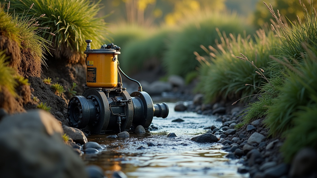
Build a micro-hydro power system: site assessment, matching turbine type to your water, penstock design, and installing the generator.
title: "Micro-Hydro Power" subtitle: "Continuous Electricity from Moving Water — Site Assessment Through Grid-Independent Generation" author: "Nored Farms" date: "2026"
Content Extraction Summary
**Hook Options:** 1. A 2-inch pipe dropping 50 feet with the flow of a garden hose produces more annual kWh than a $30,000 rooftop solar array — and it does it at 2 AM in January. 2. The average American home uses 30 kWh per day. A creek dropping 100 feet at 50 gallons per minute generates 33 kWh per day, 24 hours a day, 365 days a year, for a total system cost under $5,000. 3. Water wheels powered every flour mill, sawmill, and textile factory in America before 1900. The technology did not become obsolete — it became unfashionable.
**Key Mechanism:** Gravitational potential energy converted to rotational kinetic energy via turbine, then to electricity via permanent magnet alternator. Power output is a direct function of vertical drop (head) and volumetric flow rate. Unlike solar and wind, the energy source is continuous and predictable, producing a stable baseload.
**Misconception to Correct:** Most people assume micro-hydro requires a large river or dam. In reality, a small year-round stream with modest vertical drop — conditions common across Appalachia, the Pacific Northwest, the Ozarks, and the Hill Country — can power a household. Head matters more than flow volume. A trickle falling 200 feet produces more power than a lazy creek with zero drop.
**Practical Application:** For any rural property with a year-round stream and at least 10 feet of vertical drop within a manageable pipe run, micro-hydro is the most cost-effective renewable energy source available — lower cost per kWh than solar, wind, or grid connection in remote locations. A DIY system using off-the-shelf components can be built in a weekend.
**Citation-Ready Claims:**
- Micro-hydro capacity factor ranges 40–90%, compared to 10–25% for residential solar and 25–45% for small wind (US DOE, Energy Efficiency & Renewable Energy Office, "Microhydropower Systems," 2023).
- Global installed small hydro capacity exceeded 78 GW by 2019 (IRENA, "Renewable Energy Statistics 2020").
- The Pelton wheel, patented in 1878, improved water turbine efficiency from roughly 40% to over 90% — the largest single jump in hydroelectric conversion efficiency in history (Pelton, L.A., US Patent 233,692, 1880).
- A micro-hydro system producing 1 kW continuous output generates 8,760 kWh/year — equivalent to a 6 kW solar array in a location averaging 4 peak sun hours per day (NREL, PVWatts Calculator comparison).
- FERC exempts hydropower projects under 100 kW from licensing requirements under the Energy Policy Act of 2005, 18 CFR 4.105.
1. Introduction — The Oldest Renewable Energy Source Still Works Better Than the Newest Ones
A 1 kW micro-hydro system running 24 hours a day produces 8,760 kWh per year. A 1 kW solar panel in most of the United States produces 1,200–1,800 kWh per year. Same rated capacity. Five to seven times the actual output. The math is not subtle.
Micro-hydro does not depend on weather, season, time of day, or cloud cover. It produces power while you sleep. It produces power in December. It produces power during the week-long overcast stretches that flatten solar arrays and drain battery banks. For any property with a year-round stream and vertical drop, micro-hydro is the most reliable, least expensive, and most overlooked source of off-grid electricity available.
The technology is ancient. Water wheels powered grain mills across the Roman Empire. By the 11th century, the Domesday Book recorded over 6,000 water mills operating in England — roughly one for every 300 people. The American Industrial Revolution ran on waterpower before it ran on coal. Lowell, Massachusetts built its entire textile economy on canal-fed water turbines. Every small town in Appalachia, the Ozarks, the Piedmont, and the Hill Country once had a mill creek with a wheel on it.
The transition from water wheels to turbines happened in the 19th century. James B. Francis developed the Francis turbine in 1848 — an inward-flow reaction turbine suited to medium head and medium flow, still the most widely installed turbine type on Earth. Lester Pelton patented his impulse turbine in 1878, designed for high-head sites where a jet of water strikes curved buckets on a wheel. The Pelton wheel raised turbine efficiency from around 40% to over 90% in a single design leap. Fritz Ossberger patented the crossflow turbine in 1933, optimized for sites with variable flow — water enters across the top of a cylindrical runner and exits across the bottom, passing through the blades twice for additional energy extraction.
Modern micro-hydro systems use the same physics as a 200 MW dam. The difference is scale. A dam impounds millions of gallons and drops it through massive turbines. A micro-hydro system collects a fraction of a stream's flow, runs it through a pipe to gain velocity from vertical drop, and directs it through a turbine the size of a dinner plate connected to a permanent magnet alternator. The turbine spins. The alternator generates AC current. The current charges batteries or feeds an inverter. The house has power.
**Why this matters now.** Rural grid connection costs $15,000–$50,000 per mile of new line in rough terrain. Solar-plus-battery systems sized for whole-home backup run $25,000–$60,000 installed. A micro-hydro system producing 1–3 kW continuous — enough for a typical off-grid home — costs $2,000–$8,000 in materials and can be self-installed. The break-even against grid connection is often immediate if the nearest pole is more than a quarter mile away.
2. Site Assessment — Measuring What You Have
Two numbers determine your power output: **head** and **flow**. Everything else — turbine selection, pipe sizing, electrical configuration — follows from these measurements.
The Power Equation
The fundamental equation for hydroelectric power:
**P = Q x H x g x n**
Where:
- **P** = power output in watts
- **Q** = flow rate in cubic meters per second (m3/s)
- **H** = net head (vertical drop minus friction losses) in meters
- **g** = gravitational acceleration (9.81 m/s2)
- **n** = system efficiency (typically 0.50–0.70 for micro-hydro after accounting for turbine, drive, and generator losses)
For US customary units, the practical formula is:
**P (watts) = H (feet) x Q (gallons per minute) / k**
Where k = 5.3 for a well-designed system (roughly 53% overall efficiency) or k = 4.3 for a high-efficiency system (roughly 65% overall efficiency). Use k = 5.3 for planning — it is conservative and accounts for real-world friction losses, turbine inefficiency, and electrical conversion losses.
Worked Examples
**Example 1 — Modest Hill Country creek:**
- Head: 30 feet of vertical drop over 400 feet of horizontal run
- Flow: 25 gallons per minute (a small but year-round spring-fed creek)
- P = 30 x 25 / 5.3 = **142 watts continuous**
- Annual output: 142 x 8,760 hours = **1,244 kWh/year**
- Context: Enough for LED lighting, refrigerator, laptop charging, and a chest freezer. Not enough for electric heating, AC, or an electric range.
**Example 2 — Appalachian hollow with real drop:**
- Head: 100 feet of vertical drop
- Flow: 50 gallons per minute
- P = 100 x 50 / 5.3 = **943 watts continuous**
- Annual output: 943 x 8,760 = **8,261 kWh/year**
- Context: Exceeds the average US household consumption of 10,500 kWh/year when combined with modest conservation. This is full household power from a pipe and a turbine.
**Example 3 — High mountain site:**
- Head: 300 feet
- Flow: 30 gallons per minute
- P = 300 x 30 / 5.3 = **1,698 watts continuous**
- Annual output: 1,698 x 8,760 = **14,874 kWh/year**
- Context: Surplus power. Run the house, charge an EV, heat water electrically, sell excess to the grid if interconnection is available.
**Example 4 — Marginal low-head site:**
- Head: 8 feet
- Flow: 200 gallons per minute
- P = 8 x 200 / 5.3 = **302 watts continuous**
- Annual output: 302 x 8,760 = **2,645 kWh/year**
- Context: Viable for a cabin or as a supplement to solar. Low-head sites need high flow to compensate — and a different turbine type.
Measuring Head
Head is the vertical distance the water falls. Not the length of the pipe. Not the distance along the hillside. Vertical drop only.
**Method 1 — Altimeter or GPS.** Stand at the proposed intake point and record the elevation. Walk to the proposed turbine location and record again. The difference is gross head. GPS altimeters are accurate to plus or minus 10–30 feet, which is not good enough for serious design. Use this for initial screening only.
**Method 2 — Water level and hose.** Run a garden hose from the intake area downhill. Attach a pressure gauge to the lower end. Fill the hose with water and eliminate air bubbles. Read the pressure in psi and multiply by 2.31 to convert to feet of head. A reading of 43 psi equals approximately 100 feet of head. This method is accurate to within 1–2% and costs nothing beyond a $15 pressure gauge.
**Method 3 — Surveyor's level or laser level.** Set up a level on a tripod. Sight a measuring rod at the lower location. Move in increments down the slope, recording each vertical drop. Sum the increments. This is the most accurate field method, yielding measurements within inches.
Measuring Flow
**Method 1 — Bucket and stopwatch.** Build a temporary weir or dam to concentrate all stream flow through a single point. Catch the full flow in a 5-gallon bucket. Time how long it takes to fill. If the bucket fills in 12 seconds: (5 gallons / 12 seconds) x 60 = 25 gallons per minute. Repeat three times and average. This is accurate for flows under 50 GPM.
**Method 2 — Weir measurement.** For larger streams, build a temporary weir — a board or plywood sheet spanning the full channel width with a rectangular or V-shaped notch cut in the top. Measure the depth of water flowing over the notch. Standard weir formulas convert depth-over-notch to flow rate. A 90-degree V-notch weir with 6 inches of water flowing over it passes approximately 65 GPM. Weir tables are published by the USGS and the Bureau of Reclamation.
**Method 3 — Float method.** Measure a straight 20-foot section of the stream. Drop a float (orange, stick, leaf) and time how long it takes to travel the 20 feet. Measure the average cross-sectional area of the stream in that section (width x average depth). Velocity (feet/second) = 20 / time. Flow = velocity x cross-section area x 0.8 correction factor (to account for slower water near the bed). Convert cubic feet per second to GPM by multiplying by 449.
**Critical: Measure at the lowest flow of the year.** Your system must be designed for the driest month, not the spring flood. If possible, measure flow in late summer or early fall. If you cannot wait, ask neighbors with long memories when the creek has run lowest. Some USGS gauging stations have decades of flow data for nearby streams — check the USGS National Water Information System before building anything.
Minimum Viable Sites
A site is worth developing if:
- Year-round flow of at least 5 GPM (seasonal streams are not viable for baseload power)
- At least 10 feet of net head within a reasonable pipe run (under 1,000 feet)
- The resulting power output exceeds 50 watts continuous (about 440 kWh/year — enough to be worth the effort for lighting and device charging)
- The intake and turbine locations are accessible for construction and maintenance
Below 50 watts continuous, a solar panel and battery is simpler.
3. Turbine Types — Matching the Machine to the Water
Turbines divide into two families: **impulse** turbines (water jet hits buckets in open air) and **reaction** turbines (runner is submerged, pressure drop happens across the blades). The choice depends entirely on head and flow.
Impulse Turbines — High Head, Low Flow
**Pelton Wheel.** One or more water jets strike curved split-buckets on a wheel. The water reverses direction as it hits the bucket, transferring nearly all its kinetic energy. Best for heads above 50 feet with flows under 100 GPM. A 4-inch Pelton wheel with two nozzles at 200 feet of head and 20 GPM produces approximately 750 watts. The Pelton is the simplest turbine to build, maintain, and repair. No submerged bearings. No seals. No draft tube. The runner spins in air. Nozzles are adjustable to match changing flow — partially close a nozzle to reduce flow without shutting down.
Peak efficiency: 85–90%. DIY buildability: High. Pelton runners can be cast from aluminum, machined from steel, or purchased off the shelf from suppliers like PowerSpout, Energy Systems & Design, and Harris Hydro.
**Turgo Turbine.** Similar to a Pelton but the jet enters from the side at an angle, striking one face of each bucket and exiting the other side. This allows a smaller runner diameter for the same power, which means faster rotation — useful for direct-drive to standard alternators without gearing. Best for heads of 30–300 feet and flows of 10–200 GPM. Slightly lower peak efficiency than a Pelton (80–85%) but more tolerant of silty water because debris passes through rather than lodging in a split bucket.
Crossflow Turbines — Medium Head, Medium to High Flow
**Crossflow / Banki-Mitchell / Ossberger Turbine.** Water enters through a rectangular nozzle, passes through a cylindrical drum-shaped runner with curved blades, crosses the open interior, and passes through the blades a second time on the way out. The two-pass design extracts energy twice, maintaining high efficiency (75–85%) across a wide range of flows — from 20% to 100% of design flow. This flat efficiency curve makes the crossflow ideal for streams with variable seasonal flow. The nozzle can be divided into two sections (typically 1/3 and 2/3) to further improve part-flow performance.
Best for heads of 5–100 feet and flows of 50–2,000 GPM. DIY buildability: Moderate. The runner can be fabricated from flat steel blades welded between two end discs. Plans are available from multiple open-source sources. More complex than a Pelton but well within a competent welder's capability.
Reaction Turbines — Low Head, High Flow
**Francis Turbine.** Water enters a spiral casing surrounding the runner, passes through adjustable guide vanes, flows inward through the runner blades, and exits downward through a draft tube. The Francis turbine operates fully submerged under pressure. It is the dominant turbine in commercial hydropower — roughly 60% of all installed hydro capacity worldwide uses Francis turbines. At micro-hydro scale (under 100 kW), Francis turbines are less common because they require precise manufacturing, are expensive to build, and are intolerant of debris. Efficiency peaks at 90–95% but drops sharply below 60% of design flow.
Best for heads of 30–500 feet and flows of 100–10,000+ GPM. DIY buildability: Low. Precision casting or machining required.
**Propeller / Kaplan Turbine.** An axial-flow turbine resembling a ship's propeller in a tube. Water flows straight through the runner. The Kaplan variant has adjustable blade pitch to maintain efficiency across varying flows. Propeller turbines are the only efficient option for very low head sites — 3 to 30 feet — with high flow volumes.
Best for heads of 3–30 feet and flows of 200–10,000+ GPM. DIY buildability: Moderate for fixed-pitch propeller versions. Open-source designs exist for 3D-printed and machined propeller runners for heads under 10 feet.
Turbine Selection Chart
| Head (feet) | Flow (GPM) | Recommended Turbine | Typical Efficiency | |---|---|---|---| | 3–15 | 200–5,000+ | Propeller / Kaplan | 75–90% | | 5–100 | 50–2,000 | Crossflow (Banki) | 75–85% | | 15–50 | 50–500 | Turgo | 80–85% | | 50–1,000+ | 5–200 | Pelton | 85–90% | | 30–500 | 100–5,000+ | Francis | 90–95% |
For most DIY micro-hydro installations on rural property, the Pelton or crossflow will be the right choice. Pelton for high-head/low-flow sites (steep terrain, long pipe runs). Crossflow for medium-head/variable-flow sites (wider valleys, seasonal creeks with spring surges).
4. Penstock Design — The Pipe Is the Power Plant
The penstock is the pipe that carries water from the intake to the turbine. Get it wrong and you lose your power to friction before the water ever reaches a blade. Penstock design is where most DIY micro-hydro projects fail or underperform.
Pipe Sizing — The Friction-Loss Tradeoff
Larger pipe = less friction loss = more power delivered. But larger pipe costs more, weighs more, and is harder to install on a steep hillside. The engineering rule of thumb: **keep friction losses below 10% of gross head.** Losing 20–30% to friction in an undersized pipe is the single most common mistake.
Friction loss depends on pipe diameter, pipe length, flow rate, and pipe material roughness. The Hazen-Williams equation or Darcy-Weisbach equation provides exact numbers. For planning purposes:
| Pipe Diameter (inches) | Maximum Flow for <10% Loss per 100 feet | |---|---| | 2 | 15–20 GPM | | 3 | 40–60 GPM | | 4 | 80–120 GPM | | 6 | 250–400 GPM | | 8 | 500–800 GPM |
**Example:** A site with 100 feet of head, 50 GPM flow, and a 500-foot pipe run. Using 3-inch PVC (C=150), friction loss is approximately 12 feet over 500 feet — a 12% loss, slightly above target. Moving to 4-inch PVC drops friction loss to approximately 3 feet — a 3% loss. The 4-inch pipe costs roughly $2 per foot more ($1,000 total) but recovers 9% of head, which at 50 GPM translates to roughly 85 additional watts of continuous output. Over ten years, those 85 watts produce 7,446 kWh. At $0.15/kWh grid value, that is $1,117 in recovered energy — the pipe upgrade pays for itself.
Pipe Materials
**PVC (Schedule 40 or SDR-26).** Cheapest option. Light, easy to join with solvent cement. Pressure rated to 160–200 psi (adequate for heads up to 350–450 feet). Degrades in UV sunlight — bury it or paint it. Becomes brittle in hard freezes if empty. Maximum practical diameter: 8 inches for portability. Best for heads under 300 feet and moderate temperatures.
**HDPE (High Density Polyethylene).** Flexible, available in long coils (reducing joint count), and UV resistant. More expensive than PVC per foot but dramatically faster to install on rough terrain — it bends around obstacles instead of requiring elbows at every turn. Fused joints are stronger than PVC cement joints. Best for rough terrain, long runs, and cold climates.
**Steel.** Required for very high head applications (above 400 feet) where pressures exceed PVC/HDPE ratings. Heavy, expensive, requires welding or flange connections. Corrosion is a maintenance concern — interior coating or cathodic protection adds cost. Used primarily in professional installations above 10 kW.
Intake Design
The intake structure serves three functions: divert water from the stream into the penstock, keep debris out, and allow excess water to bypass back to the stream.
**Trash rack.** A screen or grate at the intake prevents leaves, sticks, and gravel from entering the pipe. Use stainless steel or aluminum bar grating with 1-inch spacing for most applications. The rack must be removable for cleaning — this is a regular maintenance item, especially during fall leaf drop.
**Settling basin.** A small pool between the intake and the penstock entrance allows sand and silt to settle out before entering the pipe. Size it so the water velocity drops below 1 foot per second, giving particles time to settle. A basin 4 feet long, 2 feet wide, and 2 feet deep is adequate for flows under 100 GPM. Install a drain valve at the bottom for periodic flushing.
**Overflow.** The intake must include a spillway or overflow pipe that returns excess water to the stream. During high water events, the intake will collect more water than the penstock can handle. Without an overflow, the intake structure floods, erodes, and eventually fails.
Surge Control
When a turbine valve closes suddenly — whether intentionally or due to a blockage — the water in the penstock decelerates rapidly. This creates a pressure wave called **water hammer** that travels back up the pipe at roughly 3,000–4,000 feet per second. The peak pressure can exceed the pipe's burst rating, splitting PVC joints or blowing off fittings.
Mitigation strategies:
- **Slow-closing valves.** Never use quarter-turn ball valves at the turbine. Use gate valves or globe valves that require multiple turns to close.
- **Pressure relief valve.** Install a spring-loaded pressure relief valve near the turbine, set to open at 80% of the pipe's rated pressure.
- **Standpipe or surge tank.** An open-top vertical pipe connected to the penstock near the turbine. When pressure rises, water rises in the standpipe instead of stressing the pipe. The standpipe height must equal or exceed the static head — which limits this approach to lower-head systems.
- **Gradual nozzle deflection.** On Pelton systems, the nozzle deflector diverts the jet away from the runner before closing the needle valve, preventing sudden flow stoppage.
5. Electrical Generation — Turning Rotation into Usable Power
Generator Types
**Permanent Magnet Alternator (PMA).** The default for DIY micro-hydro. A rotor with rare-earth magnets (neodymium) spins inside a stator with copper windings. No brushes. No excitation circuit. No slip rings. Output is wild three-phase AC at a frequency proportional to rotation speed. PMAs are available from micro-hydro suppliers (PowerSpout, Harris Hydro, Energy Systems & Design) or can be built from scratch using plans from Hugh Piggott's widely referenced "A Wind Turbine Recipe Book" — the same alternator design works for both wind and hydro with different mounting.
Output voltage varies with RPM. A 48V nominal PMA might produce 20V at low speed and 120V at high speed. This variable output is managed by the charge controller or rectifier downstream.
**Induction Motor as Generator.** A standard AC induction motor (the kind found in every workshop air compressor) can be run as a generator by spinning it faster than its synchronous speed and providing reactive power via a capacitor bank. This is the cheapest path to a generator if you have a surplus motor. Limitations: narrow RPM window for stable output, requires load to be closely matched, and producing reactive power from capacitors limits practical size. Works well for grid-tied micro-hydro where the grid supplies reactive power and sets frequency.
**Automotive Alternator.** Cheap, available everywhere, and familiar. Output is 12V or 24V DC. Major disadvantage: the field coil draws power (reducing efficiency by 5–15%), brushes wear and require replacement, and maximum practical output is 1,500–2,000 watts before the alternator overheats. Acceptable for systems under 500 watts. Not recommended for serious installations.
Voltage Regulation and Load Control
A micro-hydro system produces power 24/7 whether you are using it or not. The turbine and stream do not know or care about your load. If you turn off every light and appliance in the house, the turbine keeps spinning at the same speed, the alternator keeps generating, and the energy has to go somewhere.
**Electronic Load Controller (ELC) / Dump Load.** This is the key device in any micro-hydro electrical system. The ELC monitors the turbine's output (voltage or frequency) and diverts excess power to a **dump load** — typically a bank of water heating elements in a hot water tank. When household demand drops, the ELC sends more power to the dump load. When demand rises, the ELC reduces the dump load. The turbine always sees a constant load, runs at constant speed, and produces stable voltage and frequency.
Result: free hot water as a byproduct of voltage regulation. A 1 kW system with typical household load patterns will dump 40–60% of its power to hot water. A 1,000-watt dump load in a well-insulated 80-gallon tank raises water temperature by roughly 7 degrees Fahrenheit per hour.
**Battery-Based Systems.** For smaller systems (under 1 kW), the output can be rectified to DC and used to charge a battery bank (typically 24V or 48V). A charge controller manages the battery charging and diverts excess to a dump load when batteries are full. An inverter converts battery DC to 120/240V AC for household use. This is the same architecture as solar, and micro-hydro can share the same battery bank and inverter as an existing solar system — simply add the hydro input through a second charge controller.
**Direct AC Systems.** For larger systems (1–10 kW) with an ELC, the alternator output can be regulated to produce utility-grade 120/240V AC at 60 Hz directly, without batteries. This eliminates the cost and maintenance of a battery bank. The ELC holds frequency stable by modulating the dump load. The drawback: if the turbine stops (intake clogged, pipe burst, maintenance shutdown), there is no stored energy — the power goes out immediately. Most systems include at least a small battery bank for ride-through during brief interruptions.
Transmission from Powerhouse to Home
Micro-hydro powerhouses are often located at the bottom of a hill, hundreds or thousands of feet from the house. Long wire runs at low voltage suffer high losses. The solution: transmit at higher voltage.
For battery-based systems, use 48V instead of 12V — this reduces wire losses by a factor of 16 for the same wire gauge. For direct AC systems, the alternator may produce 240V single-phase, which tolerates longer runs than 120V. For very long runs (over 1,000 feet), a step-up transformer at the powerhouse and a step-down transformer at the house can push transmission voltage to 480V or higher, keeping losses below 5%.
Wire sizing follows standard voltage drop calculations. Target less than 5% voltage drop. Copper wire at current prices makes long low-voltage runs expensive — another argument for higher transmission voltage.
6. Installation — Building the System
Intake Structure
Locate the intake at a natural constriction or pool where water is deep enough to submerge the penstock entrance by at least 6 inches below the surface at minimum flow. This prevents air from entering the pipe — air in a penstock dramatically reduces power output and can cause destructive surging.
Build the intake from concrete, treated lumber, or stacked stone with concrete cap. The structure must survive the 100-year flood for your stream. Anchor it to bedrock or into the bank below scour depth. Install the trash rack vertically at a 60–70 degree angle from horizontal so debris slides off during high water instead of accumulating.
Penstock Routing
Follow the terrain. Avoid spanning unsupported gaps longer than 20 feet without support blocks. Bury the pipe at least 12 inches deep where possible — this protects against UV, mechanical damage, livestock, and freeze damage. Where the pipe must cross exposed terrain, support it on concrete saddles or treated timber cradles at 10-foot intervals.
Avoid sharp bends. Every elbow creates turbulence and friction loss. Use long-sweep bends (large radius) instead of standard 90-degree elbows. If the penstock must change direction sharply, use two 45-degree elbows with a straight section between them.
Anchor the pipe at every bend and at 100-foot intervals on straight runs. Thermal expansion and contraction of PVC can generate significant force over a 500-foot run. Thrust blocks at bends prevent the pipe from walking off its supports.
Powerhouse
The powerhouse is a small structure at the base of the penstock enclosing the turbine, generator, electrical controls, and tailrace outlet. Size it to allow working room around all components — 8 x 8 feet is typical. Build the floor at least 12 inches above the expected high water mark of the tailrace. Install drainage and ventilation. The powerhouse will be humid from spray — protect electrical components in NEMA 4X enclosures.
Mount the turbine and generator on a concrete pad or heavy steel frame. Alignment between the turbine shaft and generator shaft must be precise (within 0.005 inches) to prevent bearing failure. Belt drive (V-belt or timing belt) between turbine and generator provides speed matching and absorbs minor misalignment, and is the preferred approach for DIY installations.
Tailrace
The tailrace returns water from the turbine to the stream. It must be sized to handle full flow without backing up — if the tailrace floods, it submerges the turbine runner, destroying efficiency. A simple open channel lined with gravel or concrete is sufficient. Discharge the tailrace into the original stream channel at least 50 feet below the intake to prevent recirculation.
7. Safety
**Drowning.** Intakes, headponds, and settling basins are drowning hazards. Fence them. Cover them with grating rated for the expected load (foot traffic, livestock). Post signage. A 2-foot-deep settling basin with slippery concrete walls and cold water has killed people.
**Electrical grounding.** The powerhouse contains a generator producing potentially lethal voltage. Ground the generator frame, all metal enclosures, and the penstock (if metal) to a driven ground rod. Install GFCI protection on all circuits downstream of the inverter. Follow NEC Article 705 for interconnection with other power sources or the grid.
**Penstock burst.** A 4-inch PVC pipe at 100 feet of head contains water at 43 psi. At 300 feet of head, that rises to 130 psi. A burst penstock at high pressure releases water with lethal force and can excavate the hillside beneath it in minutes. Use pipe rated to at least twice the maximum static pressure (including water hammer). Test all joints at full static pressure before backfilling. Never stand directly below an exposed pressurized penstock during testing.
**Water hammer.** Covered in Section 4. The summary: never close a valve quickly on a loaded penstock. Install pressure relief. Use slow-closing valves. A water hammer event at 300 feet of head can spike pressure to 600+ psi — enough to shatter Schedule 40 PVC.
**Freeze protection.** In climates where sustained freezing occurs:
- Bury the penstock below frost depth (4–6 feet in northern states)
- Insulate exposed sections with closed-cell foam
- Keep water flowing — moving water in an insulated pipe resists freezing at temperatures well below 32 degrees F
- Install a drain valve at the penstock's lowest point for winter shutdown if the stream freezes
- Drain the penstock completely before a hard freeze if the system will be idle — ice expansion bursts pipes
8. Permits and Water Rights — The Legal Landscape
Micro-hydro permitting is a patchwork. Federal, state, and local requirements vary by location, stream classification, and system size.
Federal — FERC
The Federal Energy Regulatory Commission (FERC) has jurisdiction over all hydropower in the United States. However, FERC provides a **conduit exemption** for systems under 40 MW using existing conduits (irrigation canals, municipal water pipes) and a **small hydropower exemption** for systems under 10 MW on non-federal lands. For micro-hydro under 100 kW, 18 CFR 4.105 provides a simplified exemption process. Filing is free. Response time is typically 60–90 days.
If your system does not connect to navigable waters and does not affect interstate commerce, FERC jurisdiction may not apply at all. Many states have interpreted this to mean that small off-grid systems on private property with non-navigable streams do not require FERC filings. Consult a water rights attorney in your state.
State Water Rights
Western states (prior appropriation doctrine): you must file for a water right to divert any water, even if you return it to the stream 100 feet downstream. The application specifies the diversion point, the amount of water, the beneficial use, and the return point. Processing times vary from 30 days (Colorado small use) to 2+ years (California). Some states have simplified "small hydro" permits — Montana's Renewable Energy Permit covers systems under 100 kW with a streamlined one-page application.
Eastern states (riparian rights doctrine): landowners have a right to reasonable use of water flowing through their property. Micro-hydro diversions that return all water to the stream within the same property typically qualify as reasonable use without a permit. Confirm with your state environmental agency.
Environmental Considerations
**Fish passage.** If your stream contains any fish species — game fish, native species, or listed threatened/endangered species — you may need to provide upstream and downstream fish passage at your intake. A simple fish screen (1/4-inch mesh) across the intake opening prevents entrainment. A bypass flow that maintains a minimum depth in the natural channel around your diversion ensures passage.
**Minimum instream flow.** Many permits require leaving a minimum flow in the natural channel below your diversion point. This is typically 50–80% of the dry-season flow. Your system design must account for this — if the creek flows 50 GPM in August and your permit requires 30 GPM instream flow, you can only divert 20 GPM.
**Sediment and erosion.** Construction activities near waterways trigger erosion control requirements in most states. Use silt fencing, straw bales, and temporary seeding during construction. Restore the stream bank after intake installation.
9. Maintenance — Keeping the Water Flowing
Micro-hydro systems have far fewer maintenance requirements than solar (inverter replacement, panel cleaning, battery cycling) or wind (blade inspection, yaw bearing lubrication, tower climbing). The turbine has one moving part. The generator has one moving part. The pipe has no moving parts.
Regular Schedule
**Daily (first month) / Weekly (after):**
- Check trash rack for debris. Clear as needed. During fall leaf drop, daily clearing may be required.
- Listen for unusual sounds from the turbine and generator (grinding, knocking, cavitation whine).
- Check power output at the meter. A drop in output with no change in stream flow indicates a blockage, air leak, or bearing issue.
**Monthly:**
- Inspect penstock for leaks at joints. Even small drips indicate a developing failure.
- Check belt tension and wear (if belt-driven).
- Flush the settling basin by opening the drain valve.
- Check dump load elements for continuity — a failed dump load element will cause voltage or frequency spikes.
**Annually:**
- Lubricate generator bearings (if greaseable — many PMAs use sealed bearings with 5–10 year service life).
- Replace brushes (if using an induction generator or automotive alternator).
- Inspect penstock interior at the intake end for sediment buildup. Flush by disconnecting from the turbine and opening the pipe fully.
- Inspect intake structure for erosion, settling, or damage from high water events.
- Test the pressure relief valve by manually activating it.
- Check all electrical connections for corrosion, especially in the humid powerhouse environment.
**Every 5–10 years:**
- Replace turbine nozzle tips (Pelton/Turgo) if worn by abrasive sediment.
- Rebush or replace turbine bearings.
- Resurface runner buckets if erosion has reduced efficiency (noticeable as a 10–20% drop in output at unchanged head and flow).
Seasonal Shutdown
In climates with sustained freezing, a controlled winter shutdown may be necessary if the stream freezes or flow drops below usable levels.
Shutdown procedure: 1. Close the intake valve slowly over 60 seconds. 2. Open the penstock drain valve at the lowest point. 3. Disconnect the generator from the load. 4. Drain all water from the penstock completely — even a low spot holding a cup of water will freeze, expand, and crack the pipe. 5. Cover the intake with a board or tarp to prevent debris accumulation.
Spring startup: 1. Inspect the full penstock run for winter damage (frost heave, fallen trees, animal damage). 2. Clear the intake trash rack and settling basin. 3. Close the drain valve. 4. Open the intake valve slowly. Let the pipe fill completely and check for leaks before reconnecting the generator. 5. Reconnect the generator to the load. Monitor output for 24 hours before leaving the system unattended.
Troubleshooting Quick Reference
| Symptom | Likely Cause | Fix | |---|---|---| | Output dropped 20–50% | Partial penstock blockage or air leak at intake | Inspect trash rack, check pipe joints, verify intake is submerged | | Output dropped to zero | Full blockage, tripped breaker, or broken belt | Walk the penstock, check electrical panel, inspect belt | | Turbine vibration | Worn bearings, debris in runner, misalignment | Inspect runner for lodged debris, check bearing play, realign | | Generator overheating | Dump load failure (full load on generator), low airflow | Check dump load elements, clean generator ventilation | | Water hammer noise | Valve closed too fast, pressure relief failed | Install slow-close valve, test/replace pressure relief | | Voltage fluctuation | ELC malfunction, intermittent dump load connection | Test ELC, check dump load wiring connections |
10. Sources
1. US Department of Energy, Office of Energy Efficiency & Renewable Energy. "Microhydropower Systems." energy.gov. Accessed 2026. 2. IRENA. "Renewable Energy Statistics 2020." International Renewable Energy Agency, Abu Dhabi, 2020. 3. Pelton, Lester A. "Water Wheel." US Patent 233,692. October 26, 1880. 4. National Renewable Energy Laboratory. "PVWatts Calculator." pvwatts.nrel.gov. Accessed 2026. 5. Federal Energy Regulatory Commission. 18 CFR Part 4, Subpart K — "Exemption of Small Hydroelectric Power Projects of 10 Megawatts or Less." 2005. 6. Piggott, Hugh. "A Wind Turbine Recipe Book." Scoraig Wind Electric, 2016. (Alternator construction plans applicable to hydro.) 7. Davis, Scott. "Microhydro: Clean Power from Water." New Society Publishers, 2003. 8. Inversin, Allen. "Micro-Hydropower Sourcebook." Intermediate Technology Publications, 1986. 9. Paish, Oliver. "Small Hydro Power: Technology and Current Status." Renewable and Sustainable Energy Reviews, vol. 6, 2002, pp. 537–556. 10. Harvey, Adam et al. "Micro-Hydro Design Manual." Intermediate Technology Publications, 1993. 11. US Bureau of Reclamation. "Water Measurement Manual." 3rd ed., revised 2001. 12. USGS National Water Information System. "Surface Water Data." waterdata.usgs.gov. Accessed 2026. 13. National Electrical Code, NFPA 70, Article 705 — "Interconnected Electric Power Production Sources." 2023.
`[practical-skills]` `[facility-design]` `[advanced]`