garden-design
Pole Barn Construction
A comprehensive guide covering Pole Barn Construction.
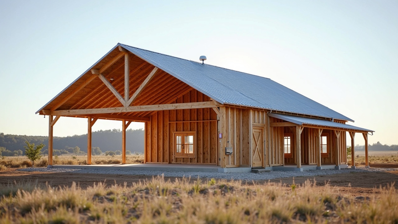
A Complete Guide to Post-Frame Building
Pure Euphoria Botanicals · Nored Farms · Austin, Texas
1. Introduction — The Most Building for the Least Money
Every enclosed structure starts with the same engineering problem: transfer the weight of the roof and the force of the wind down to the ground without the building falling over. Conventional construction solves this with a continuous concrete foundation, sill plates bolted to the concrete, stud walls built on top of the sill plates, and a roof system sitting on top of the stud walls. Every one of those steps costs money, requires precision, and adds time.
Post-frame construction skips most of it. Bury posts in the ground. Nail horizontal boards between the posts to carry the wall skin. Set trusses on top of the posts. Screw on metal panels. The building is enclosed.
This is not a shortcut. It is older than stick framing. Timber-frame barns in Europe used earthfast posts for centuries before the balloon frame was invented in Chicago in the 1830s. The modern pole barn — round poles replaced by square treated posts, nailed girts replacing mortise-and-tenon joinery, prefabricated trusses replacing hand-cut rafters — emerged in the 1930s when the USDA and land-grant universities developed standardized designs for farm buildings that could be erected by the farmer without a general contractor.
The cost advantage is structural, not cosmetic. A pole barn is cheaper because it uses less material and fewer labor hours to enclose the same volume. No concrete forms. No rebar. No anchor bolts. No sill plate. No continuous footing. No stem wall. The posts bear directly on the soil (or on a buried pier), and the wall cladding spans between posts without needing studs at 16-inch centers. A 30×40-foot pole barn uses roughly 40% less lumber than a comparably sized stick-frame building and 80% less concrete.
What this guide covers. Every step from site layout through hanging the last panel. Design decisions that affect cost and durability. Foundation options for different soil types. Post selection, sizing, and embedment. Framing with girts, purlins, and trusses. Metal panel installation for roof and walls. Door types and header sizing. Optional concrete floor with proper drainage. Electrical rough-in and insulation for conditioned use. A reader with basic carpentry skills should be able to build a pole barn start to finish using this document.
2. Design and Planning
Clear Span vs. Divided
The defining advantage of post-frame construction is clear span — no interior bearing walls. Posts on the perimeter carry everything. This means the interior is a single open volume that can be subdivided later with non-bearing partitions or left completely open.
Clear span limits depend on truss design. Stock trusses from most suppliers are available up to 40 feet clear span. Custom-engineered trusses can reach 60–80 feet. For a first-time builder, 24–40 feet wide is the practical range. Beyond 40 feet, truss weight and handling complexity increase significantly — a 60-foot truss weighs 400+ pounds and requires a crane or telehandler to set.
Common sizes and their uses:
- 24×32 — Two-vehicle garage or small workshop. 768 sq ft.
- 30×40 — Standard farm shop or equipment storage. 1,200 sq ft. The most common owner-built size.
- 40×60 — Large shop, hay barn, or combination building. 2,400 sq ft. Requires equipment to set trusses.
- 40×80 — Commercial-scale equipment storage or livestock confinement. 3,200 sq ft.
Eave Height
Eave height is measured from finished floor (or grade) to the bottom of the truss heel at the sidewall. This dimension controls what you can fit inside and how you use the building.
- 10 feet — Minimum for vehicle storage. Clears most pickup trucks and SUVs. Does not clear a dump truck bed in the up position.
- 12 feet — Standard for farm shops and equipment buildings. Clears a tractor with a cab and most implements. Allows a 10-foot overhead door.
- 14 feet — Required for RV storage, large equipment, or buildings that will have a loft. Allows a 12-foot overhead door.
- 16 feet — Commercial scale. Clears semi-trailers and large ag equipment.
Higher eave heights cost more — longer posts, more siding material, larger doors — but the incremental cost per additional two feet of height is surprisingly low compared to the utility gained. Build taller than you think you need. Adding height after the building is up is not feasible.
Door Placement
Plan door locations before ordering materials. Every door opening requires a header beam, and the header size depends on the opening width. Doors placed at the gable end (the triangular end wall) are structurally simpler because the truss carries the load. Doors placed in the sidewall require an engineered header to span between posts.
Rules of thumb:
- Place the largest door (typically overhead or sliding) on the gable end facing the access road or driveway.
- Place a walk-through door on the sidewall downwind from prevailing weather.
- If the building will house equipment that enters and exits frequently, consider a drive-through configuration with doors on both gable ends.
- Overhead doors wider than 16 feet require an LVL or steel header and should be engineered — do not guess on header sizing for wide openings.
Permit Requirements
Most jurisdictions require a building permit for any structure over 200 square feet. Pole barns are no exception despite persistent myths to the contrary.
What to expect:
- A site plan showing setbacks from property lines, easements, and other structures
- Foundation detail (post embedment depth, concrete collar dimensions)
- Framing plan (post spacing, truss specifications, bracing layout)
- Wind and snow load compliance for your county
- Electrical permit if wiring the building
Some rural counties have minimal enforcement and may require only a site plan and an affidavit. Others require stamped engineered drawings. Check with your county building department before buying materials. The cost of a permit ($200–$800 in most jurisdictions) is trivial compared to the cost of being ordered to tear down a non-compliant structure.
3. Foundation — Posts in the Ground
The foundation of a pole barn is not a foundation in the conventional sense. There is no continuous footing. Each post has its own isolated bearing point in the earth, and the collective resistance of all posts provides the building's stability.
Post-in-Ground (Direct Burial)
The traditional method. Dig a hole, set the post, backfill and compact. The post bears on undisturbed soil at the bottom of the hole and resists lateral forces through soil pressure against the buried portion.
Hole dimensions:
- Diameter: 12–24 inches, depending on post size and soil conditions. A 12-inch auger hole works for most 6×6 posts in competent soil. Use 18–24 inches in sandy or loose soil.
- Depth: Minimum 4 feet. Standard is 4–6 feet depending on frost depth, wind load, and eave height. The ASAE EP486.2 standard specifies minimum embedment based on building height and design wind speed.
Concrete collar (necklace footing). After setting the post plumb and braced, pour concrete around the base of the post from the bottom of the hole to 6–12 inches below grade. The concrete collar does three things: increases the bearing area at the bottom (reducing point loading on the soil), locks the post against lateral movement, and protects the below-grade portion from shifting during freeze-thaw cycles.
A typical collar uses 2–4 bags (80 lb) of premix concrete per post. For a 30×40 building with 12 posts, that is 24–48 bags total — roughly $150–$300 in concrete. Compare this to a continuous perimeter footing for the same building: 8–12 cubic yards of ready-mix at $150/yard plus forms, rebar, and labor.
Bottom bearing pad. Place a flat rock, a precast concrete pad, or pour a 4-inch concrete cookie at the bottom of the hole before setting the post. This distributes the point load across a wider area and prevents the post from slowly sinking into soft subsoil over decades.
Post-on-Pier (Surface Mount)
For buildings in areas with high water tables, expansive clay soils, or where code requires the post to be isolated from ground contact, a concrete pier is poured first and the post is bolted to the top of the pier using a post base bracket (Simpson PBS or equivalent).
Advantages: Post never contacts soil. Eliminates rot concerns entirely. Allows the use of untreated lumber for the post (though treated is still recommended for exterior exposure). Easier to replace a damaged post in the future.
Disadvantages: Requires formed and poured piers — adds cost and complexity. The bracket connection must resist uplift, which requires embedded anchor bolts and proper bracket sizing. Less forgiving of construction errors — a post buried in the ground has some tolerance for minor plumb adjustments during backfill; a post bolted to a pier is either plumb or it is not.
When to use post-on-pier: Wet sites, flood-prone areas, termite-heavy regions, or when local code prohibits direct burial. Otherwise, direct burial with a concrete collar is simpler, cheaper, and provides excellent performance for decades.
Uplift Resistance
Wind creates uplift on the roof, which tries to pull the posts out of the ground. In high-wind areas (design wind speed above 110 mph), the concrete collar alone may not provide sufficient uplift resistance.
Solutions:
- Concrete backfill to full depth — fills the entire hole with concrete instead of just a collar. Expensive but effective.
- Bottom plate or "deadman" — bolt a pressure-treated 2×6 or 2×8 crosspiece to the post at the bottom of the hole before pouring concrete. The crosspiece acts as an anchor against uplift.
- Helical ground anchors — screw-in anchors installed adjacent to the post and connected with steel cable or rod. Used in manufactured building kits.
For most buildings in zones with design wind speeds under 110 mph, a standard 4-foot embedment with a concrete collar provides adequate uplift resistance without additional measures.
4. Posts — The Structural Backbone
Treated Lumber Posts
The standard choice. Pressure-treated southern yellow pine or Douglas fir posts are available at every lumberyard in nominal 6×6 and 8×8 sizes, in lengths up to 24 feet.
Treatment levels matter. Ground-contact rated lumber is stamped UC4A, UC4B, or UC4C (Commodity Use Categories). For direct burial:
- UC4A — general ground contact, not critical structural. Adequate for fence posts, not recommended for building posts.
- UC4B — heavy-duty ground contact. The standard for pole barn posts. Requires a minimum retention of 0.60 pcf for southern yellow pine treated with copper azole (CA-C) or 0.31 pcf for micronized copper azole (MCA).
- UC4C — extreme ground contact (salt water, cooling tower). Overkill for pole barns but provides the highest retention.
Verify the treatment stamp. Look for the UC4B (or higher) designation, the treating chemical, and the retention level. Posts sold as "ground contact" without a UC4B stamp may have insufficient preservative retention for 40+ year building life.
Laminated Columns
An alternative to solid sawn posts: laminated columns made from 2× treated lumber nailed or bolted together. A 3-ply 2×6 lamination produces a column roughly equivalent in strength to a solid 6×6. A 3-ply 2×8 exceeds a solid 6×6.
Advantages of laminated columns:
- Easier to handle — three 2×8×16 boards weigh less than a solid 8×8×16.
- Can be assembled on site from standard dimensional lumber.
- Nailing girts to a laminated column is easier because the flat face provides full bearing.
- Splitting and checking (common in solid posts as they dry) is less of a structural concern in laminated members.
Disadvantages: More labor to assemble. Requires proper nailing or bolting patterns to achieve full composite action. If the laminations are not tightly fastened, the column acts as three separate boards rather than one structural member.
Nailing pattern for laminated columns (per ASAE EP559): 10d or 16d nails at 12 inches on center, staggered, in two rows. Clinch the nails (bend the points over on the exit side) for maximum shear resistance.
Post Sizing
Post size is determined by unsupported height (eave height plus embedment depth), tributary load area, and design loads (wind, snow, dead load).
General guidelines:
- 6×6 posts — adequate for buildings up to 12-foot eave height with post spacing of 8 feet or less, in areas with design wind speeds under 110 mph and ground snow loads under 30 psf.
- 8×8 posts — required for eave heights above 14 feet, post spacing above 8 feet, or high wind/snow load areas.
- Laminated 3-ply 2×8 — equivalent to 6×6 in most loading scenarios. Acceptable for buildings up to 12-foot eave.
For any building wider than 40 feet, taller than 14 feet at the eave, or located in a high-wind or heavy-snow zone, have the post sizing checked by an engineer. The cost of an engineering review ($300–$800) is cheap insurance against a structural failure.
Embedment Depth
Minimum embedment is a function of:
- Frost depth — the post must extend below the frost line to prevent heaving. Frost depth ranges from 0 inches in southern Texas to 60+ inches in Minnesota. Your county building department can provide the local frost depth.
- Lateral resistance — the post must resist wind loads by soil bearing against the embedded portion. Deeper embedment = more lateral resistance.
- Uplift resistance — as discussed in the foundation section.
Practical minimums:
- 4 feet — adequate in frost-free zones with competent soil and moderate wind.
- 5 feet — standard for most of the US. Exceeds frost depth in zones 5–7 and provides good lateral resistance.
- 6 feet — recommended for tall buildings (14+ foot eave), high-wind areas, or loose/sandy soil.
5. Framing — Girts, Purlins, Trusses, and Bracing
Girts (Wall Framing)
Girts are horizontal members that span between posts to support the wall cladding. In conventional framing, studs are vertical and carry both loads and cladding. In post-frame, the posts carry all structural loads, and the girts simply provide a nailing surface for the siding.
Sizing and spacing:
- 2×4 girts on flat (wide face against the post) — standard for metal siding with post spacing up to 8 feet.
- 2×6 girts on flat — required for post spacing above 8 feet, or when girts must also support insulation batts.
- Spacing: 24 inches on center is standard for metal siding. Reduce to 16 inches OC in the bottom 4 feet of the wall if the building will see impact loads (livestock, equipment).
Attachment: Face-nail girts to the posts with two 16d nails at each connection. For laminated columns, use structural screws (GRK, SDWS, or equivalent) instead of nails for a stronger connection.
Splash boards: The lowest girt should be a pressure-treated 2×6 or 2×8 set at grade level or just below. This "splash board" takes the most moisture and impact abuse. Some builders use a treated 2×8 skirt board at the base and standard (untreated) lumber for all girts above.
Purlins (Roof Framing)
Purlins are horizontal members that span between trusses to support the roof panels. They perform the same function on the roof that girts perform on the walls.
Sizing and spacing:
- 2×4 purlins on edge — standard for metal roofing with truss spacing of 4 feet and spans up to 8 feet.
- 2×6 purlins on edge — required for truss spacing above 4 feet or when purlins will also support ceiling insulation.
- Spacing: 24 inches on center is standard. Some metal panel manufacturers specify maximum purlin spacing based on panel profile and design loads — check the panel manufacturer's installation guide.
Attachment: Toenail purlins to the top chord of each truss with two 16d nails, or use hurricane clips (Simpson H2.5 or equivalent) for positive connection in high-wind areas.
Trusses
Trusses are the most critical structural component after the posts. They span the full width of the building without intermediate support, carry the roof dead load (panels, purlins, insulation), the live load (snow, wind, workers), and transfer all of it to the posts at the sidewalls.
Engineered vs. site-built:
- Engineered trusses (factory-built with metal connector plates) — the standard for any building over 24 feet wide. Engineered trusses are designed for specific span, spacing, and load conditions, and each truss comes with a stamped engineering drawing. Cost: $150–$500 per truss depending on span and configuration.
- Site-built trusses — acceptable for small buildings (under 24-foot span) with simple roof profiles. Site-built trusses use plywood gussets and nails instead of metal connector plates. They work, but they are not stamped, which may be a code issue in permitted buildings.
Recommendation: Use engineered trusses. The cost premium over site-built is modest ($50–$100 per truss for a 30-foot span), and the structural certainty is worth it. A truss failure during a snow load event is catastrophic and unrecoverable.
Truss spacing: 4 feet on center is standard for post-frame buildings. Some designs use 8-foot spacing with heavier purlins, but 4-foot spacing allows lighter purlins and is easier to handle during erection.
Setting trusses: For spans under 30 feet, two people can lift and set a truss by hand using a temporary vertical support at the ridge line. For spans above 30 feet, use a telehandler, skid loader with a boom attachment, or a crane. Always brace the first truss to the endwall before releasing it — an unbraced truss is dangerously unstable.
Bracing
A pole barn is a flexible structure. Without bracing, the building will rack (lean sideways) under wind load. Bracing prevents this.
Permanent bracing types:
- Diagonal corner bracing — 2×6 boards run from the top of the corner post to the third or fourth post at approximately 45 degrees. Minimum two per wall, at opposite ends.
- Metal X-bracing — flat steel straps (1.5" × 0.050") run in an X pattern between posts. Provides bracing in tension only, so the X configuration ensures one strap is always in tension regardless of wind direction.
- Diaphragm action from metal siding — properly attached metal siding provides significant racking resistance. This is real and measurable, but it should supplement dedicated bracing, not replace it.
- Continuous purlins at the ridge and eave — these act as horizontal diaphragm members, tying trusses together and preventing individual truss rollover.
Temporary bracing during erection is critical. More pole barn construction accidents involve truss collapse during erection than any other phase. Brace every truss to the preceding truss with a 2×4 diagonal before releasing it. Do not remove temporary bracing until all permanent purlins and bracing are installed.
6. Roofing — Metal Panel Installation
Metal roofing is the default for pole barns. It is lighter than shingles (reducing truss loads), lasts 40–70 years with proper installation, sheds snow effectively, and installs fast over purlins without sheathing.
Panel Types
- Exposed fastener panels (PBR profile) — the standard agricultural and commercial panel. Ribs are 1.25–1.5 inches tall, 36 inches wide, and screws go through the flat of the panel into the purlin. Cost: $1.50–$3.00 per square foot. Lifespan: 40–50 years with repainting or re-coating at 20–25 years.
- Standing seam panels — concealed fastener system where clips attach to the purlin and the panel snaps over the clip. No exposed screws on the roof surface. Cost: $4–$8 per square foot installed. Lifespan: 50–70 years. Overkill for most agricultural buildings but appropriate for a shop or conditioned space.
For a standard pole barn, exposed fastener panels (29-gauge steel, Galvalume coating) are the practical choice. They cost less, install faster, and perform well for decades.
Pitch Requirements
Minimum roof pitch for metal panels is 3:12 (3 inches of rise per 12 inches of run). Lower pitches are possible with standing seam panels and sealant at side laps, but 3:12 is the practical minimum for exposed fastener panels to prevent water infiltration at screw penetrations.
Common pitches for pole barns:
- 3:12 — low profile, least material cost, adequate for metal panels.
- 4:12 — standard. Good balance of aesthetics, snow shedding, and loft space.
- 6:12 — steeper pitch creates usable loft space for storage. Higher material cost and more challenging to work on.
Installation Sequence
- Install eave trim (drip edge) first. The bottom edge of the roof panel must overhang the eave trim by 1–2 inches to direct water into the gutter or away from the wall.
- Start panels at the gable end opposite the prevailing wind. This ensures side laps shed water with the wind rather than against it.
- Square the first panel carefully. Measure from the ridge to the eave at both ends and adjust until the panel is perpendicular to the eave. Every subsequent panel references the first one — if the first panel is crooked, every panel will be crooked.
- Overlap side laps one rib. Apply butyl sealant tape in the side lap if the pitch is below 4:12.
- Fasten with hex-head self-drilling screws with EPDM washers. Screws go in the flat of the panel (not the rib) for PBR-profile panels. Spacing: every other rib at purlins in the field, every rib at the eave and ridge. Do not over-tighten — the EPDM washer should compress slightly but not bulge beyond the edge of the screw head.
- Install ridge cap last. The ridge cap overlaps both sides of the roof by 4–6 inches. Use foam closure strips under the ridge cap to seal the corrugation profile against wind-driven rain while allowing ventilation.
Condensation Control
Metal roofing condensates on the underside whenever the panel temperature drops below the dew point — typically on clear nights when the metal radiates heat to the sky faster than the air cools. In an uninsulated pole barn, this condensation drips onto everything below.
Solutions:
- Condensation control fabric (e.g., Dripstop, MoistureLock) — a felt-like membrane factory-applied or field-applied to the underside of the panel. It absorbs condensation droplets and holds them until daytime warming evaporates them. Cost: $0.20–$0.40 per square foot added to panel cost. This is the single most cost-effective upgrade for an uninsulated pole barn.
- Ventilation — open eave and ridge details allow airflow to carry moisture out. Effective in combination with condensation fabric, insufficient alone in humid climates.
- Full insulation — eliminates condensation by keeping the panel above dew point. Required for conditioned buildings. See Section 10.
7. Siding — Wall Cladding Options
Metal Siding
The same panel used on the roof works on the walls. Install vertically (ribs running up and down) with screws into horizontal girts.
Base trim: Install a rat guard or base trim at the bottom of the wall to close the corrugation voids against rodents, wind-driven rain, and snow.
Corners: Use preformed metal corner trim. Inside corners get an L-shaped trim piece; outside corners get a J-channel or preformed outside corner piece. Seal all trim joints with butyl tape or caulk.
Cost: $1.50–$3.00 per square foot for 29-gauge painted Galvalume.
Board-and-Batten
Traditional vertical wood siding. Wide boards (1×10 or 1×12) are nailed to horizontal girts, and narrow strips (1×3 battens) cover the joints between boards. Rough-sawn lumber from a local mill works well and gives the building a classic agricultural appearance.
Post spacing for board-and-batten: 8 feet maximum. Girts at 24 inches OC, same as for metal.
Wood species: Cypress, cedar, and rough-sawn oak are naturally rot-resistant and do not require treatment for above-grade wall cladding. Pine requires paint, stain, or treatment.
Cost: $2.50–$5.00 per square foot depending on species and source. Higher than metal but preferred for aesthetic or historical reasons.
Post Spacing for Different Cladding Materials
| Cladding Material | Maximum Post Spacing | Girt Spacing | Notes |
|---|---|---|---|
| Metal panels (29 ga) | 8–10 ft | 24" OC | Standard. Adjust for wind zone. |
| Metal panels (26 ga) | 10–12 ft | 24–36" OC | Heavier gauge allows wider spacing. |
| Board-and-batten | 8 ft max | 24" OC | Wood is heavier; closer posts reduce deflection. |
| T1-11 plywood | 8 ft max | Continuous sheathing or 16" OC | Requires treated bottom edge. |
| Hardie board | 8 ft max | 16" OC | Heavy. Requires blocking at all edges. |
8. Doors — Sliding, Overhead, and Walk-Through
Sliding Doors
The traditional pole barn door. A flat panel (framed with 2×4s, skinned with metal or plywood) hangs from a track mounted above the opening and slides horizontally on rollers.
Advantages: No header load — the track is mounted to the wall above the opening and the door weight hangs from the track, not from a header beam. Simple to build. Can be made any width. Works in openings where an overhead door would not have room to retract.
Disadvantages: Requires clear wall space beside the opening equal to the door width (the door has to slide somewhere). Does not seal as tightly as an overhead door. Heavy doors require heavy-duty track and rollers.
Track and hardware: Use a steel barn door track rated for the door weight. A 12-foot-wide metal-skinned sliding door weighs 200–400 pounds. Standard residential barn door hardware is not rated for this weight — use agricultural-grade track (Burch, National, or equivalent).
Overhead (Sectional) Doors
Standard garage doors. Available in stock sizes from 8×7 to 16×8 at building supply stores, and custom sizes up to 20+ feet wide from commercial door manufacturers.
Header requirements: Overhead doors require a structural header above the opening to carry the wall and roof loads that would otherwise be carried by the wall framing removed for the opening. Header sizing depends on opening width, building height, and roof load.
| Door Width | Minimum Header |
|---|---|
| 8–10 ft | Double 2×10 or 3-ply 2×10 |
| 12 ft | Double 2×12 or LVL equivalent |
| 14–16 ft | LVL beam or steel I-beam — engineer required |
| 18+ ft | Steel beam — always engineered |
Track clearance: Standard overhead doors require 12–18 inches of clearance above the door opening for the horizontal track, plus 3–4 inches of sideroom on each side for the vertical track. Check the specific door manufacturer's clearance requirements before framing the opening.
Walk-Through Doors
Standard prehung exterior doors (36×80) fit between posts or in a framed opening within a post bay. Frame a rough opening 2 inches wider and 2 inches taller than the door unit. Use a pressure-treated sill or aluminum threshold at the bottom.
Placement: At least one walk-through door is essential for any building. Relying solely on large sliding or overhead doors for daily entry and exit wastes time and energy (heating/cooling loss in conditioned buildings). Place the walk-through on the side of the building closest to the house or primary access path.
9. Concrete Floor (Optional)
Many pole barns operate with a gravel floor for their entire life. A concrete floor is a significant added expense ($4–$8 per square foot poured and finished) and is only necessary when the building will be used as a shop, vehicle maintenance area, or conditioned space.
Gravel Pad (For Buildings Without Concrete)
Even without a concrete floor, the interior grade must be prepared properly to prevent water from pooling inside the building.
- Strip topsoil to a depth of 4–6 inches across the entire building footprint.
- Fill with compacted road base (crusite, decomposed granite, or pit-run gravel) to 4 inches above the surrounding grade. The interior should be higher than the exterior to ensure water drains out, not in.
- Top with 2–3 inches of 3/4-inch crushed stone for a firm, well-drained working surface.
Concrete Floor — Full Process
If you are pouring a concrete floor, do it after the building shell is complete. The roof protects the fresh pour from sun and rain.
Sub-grade preparation:
- Compact the existing soil with a plate compactor or roller. The sub-grade must be uniformly firm.
- Place 4 inches of compacted road base gravel over the sub-grade.
- Install a 6-mil or 10-mil polyethylene vapor barrier over the gravel. Overlap seams 12 inches and tape with poly tape. The vapor barrier prevents ground moisture from migrating through the slab.
Reinforcement:
- Wire mesh (6×6 W2.9/W2.9) — the standard for pole barn floors. Set the mesh on wire chairs or rebar bolsters so it sits in the middle third of the slab thickness (approximately 2 inches up from the vapor barrier for a 4-inch slab).
- Rebar (#3 or #4 at 24" OC both ways) — a stronger alternative for buildings that will see heavy wheel loads (forklifts, loaded trailers). More expensive and slower to install than wire mesh.
- Fiber reinforcement — polypropylene or steel fibers mixed into the concrete reduce plastic shrinkage cracking but do not replace structural reinforcement. Use in addition to, not instead of, mesh or rebar.
Slab thickness: 4 inches is standard for light-duty use (foot traffic, light vehicles). 5–6 inches for heavy equipment. 6–8 inches for buildings that will see loaded trucks or forklifts.
Control joints: Saw-cut or tooled control joints at a maximum spacing of 10 feet in each direction (or at a ratio of 2–3 times the slab thickness in feet — a 4-inch slab gets joints at 8–12 feet). Joints should be cut 1/4 of the slab thickness deep. Cut within 6–12 hours of finishing, before random shrinkage cracks form.
Slope for drainage: Slope the floor 1/8 inch per foot toward the large door opening or toward a floor drain. On a 40-foot building, that is 5 inches of fall from the back wall to the front door — enough to drain wash water and prevent standing water, not enough to notice when walking.
Pour sequence: Pour in alternating strips or bays if the building is large. A 30×40 building (1,200 sq ft) at 4 inches thick requires approximately 15 cubic yards of concrete — a single truck load. This is manageable as a single pour with a crew of 4–5 people. For buildings larger than 2,000 square feet, consider pouring in sections.
10. Electrical and Insulation Considerations
Electrical
A pole barn with any intended use beyond passive storage needs electrical service. Plan the electrical layout before closing in the walls — running wire through metal siding after the fact is frustrating and often results in code violations.
Service entrance: Size the service panel for the intended use. A 100-amp sub-panel is adequate for lighting, outlets, and a small compressor. A 200-amp panel is required if the building will power welders, large air compressors, dust collection, or HVAC equipment.
Wiring methods in pole barns:
- Surface-mounted conduit (EMT or PVC) — the easiest method for metal-sided buildings. Conduit runs along girts and posts, exposed but protected. Meets code everywhere.
- NM cable (Romex) through framed walls — acceptable only if the wall cavity is enclosed (insulated and sheathed on the interior). NM cable cannot be exposed in an unfinished building in most jurisdictions.
- UF cable — rated for direct burial and wet locations. Can be run exposed on the surface of framing members in agricultural buildings under NEC Article 547 (agricultural building wiring). Check local adoption of Article 547.
Lighting: LED high-bay fixtures at 12–16 foot spacing provide excellent shop lighting at low operating cost. A 30×40 building needs 6–8 fixtures at 150–200 watts each for a well-lit workspace. Wire all lighting on a separate circuit from outlets.
Receptacles: Install 20-amp duplex outlets every 12 feet around the perimeter, plus dedicated circuits for any fixed equipment (compressor, welder, dust collector). At least one 240-volt outlet for a welder or large motor.
Insulation
An uninsulated pole barn is a shed. An insulated pole barn is a building. The decision to insulate determines whether the structure is usable year-round in climates with temperature extremes.
Wall insulation options:
- Fiberglass batts between girts — R-13 (3.5") or R-19 (6.25") depending on girt depth. Cover the interior face with an OSB or plywood liner to protect the batts and provide a finished appearance. Cost: $0.75–$1.50 per square foot including liner.
- Spray foam (closed cell) — R-6.5 per inch. 2 inches of closed-cell foam on the interior of the metal siding provides R-13, plus a vapor barrier, plus air sealing. Cost: $2.00–$3.50 per square foot. The best-performing option but the most expensive.
- Rigid foam board — 2-inch polyiso (R-13) or XPS (R-10) attached to the interior of girts. Covered with an OSB or metal liner. Cost: $1.00–$2.00 per square foot. Good performance at moderate cost.
Roof insulation options:
- Draped radiant barrier — reflective foil draped between trusses before purlin installation. Reduces radiant heat gain by 40–50% in summer. Does not provide R-value. Cost: $0.30–$0.60 per square foot. The minimum upgrade for a building in a hot climate.
- Fiberglass batts between purlins — same approach as walls. Requires an interior ceiling liner to hold batts in place.
- Spray foam on roof panels — the most effective method. Insulates, air seals, and eliminates condensation in one step. Cost: $2.50–$4.00 per square foot of roof area.
Vapor barrier placement: In heating-dominated climates (most of the US), the vapor barrier goes on the warm side (interior) of the insulation to prevent interior moisture from condensing in the wall cavity. In cooling-dominated climates (Gulf Coast, deep South), the situation reverses — consult local practice or an insulation specialist.
11. Sources
- National Frame Building Association (NFBA) — Post-Frame Building Design Manual and industry cost data. www.nfba.org
- ASAE EP486.2 — Shallow Post and Pier Foundation Design — American Society of Agricultural and Biological Engineers standard for post embedment design.
- ASAE EP559 — Design Requirements and Bending Properties for Mechanically Laminated Columns — standard for laminated post construction.
- USDA Natural Resources Conservation Service — Agricultural Waste Management Field Handbook, Appendix 10D: Post-Frame Building Construction.
- Simpson Strong-Tie — Connectors for Post-Frame Construction — catalog of post bases, hurricane ties, and truss clips for post-frame applications. www.strongtie.com
- Metal Roofing Alliance — panel lifespan data and installation guidelines. www.metalroofing.com
- International Code Council — International Building Code (IBC) and International Residential Code (IRC) provisions for post-frame construction.
- NFBA Cost Comparison Study — post-frame vs conventional construction cost data, referenced in NFBA publications.
- American Wood Protection Association (AWPA) — Use Category System (UC) for pressure-treated wood specifications and retention levels.
- National Electrical Code (NEC), Article 547 — agricultural building wiring requirements.
Tags: [practical-skills] [facility-design] [beginner]