plants
Small Engine Repair: The Complete Practical Guide
Repair small engines: engine types, the fuel and ignition systems, compression and lubrication, and diagnosing common failures.
**Content Extraction Summary:** Covers the full scope of small engine diagnostics and repair — from fuel system teardown to compression testing, ignition troubleshooting, governor adjustment, and seasonal maintenance. Includes a text-based "won't start" diagnostic flowchart, spark plug color chart, and oil selection guide. Written for the owner who wants to fix their own mower, tiller, generator, or pump instead of paying $85/hour shop rates for a $3 carburetor gasket.
1. Introduction
Nine out of ten small engine failures trace back to the fuel system or ignition. Not the rings. Not the rod. Not the valvetrain. A 2019 Briggs & Stratton service bulletin confirmed that carburetor fouling from ethanol-blended fuel accounts for the majority of warranty claims on engines under three years old (Briggs & Stratton Service Bulletin SE-1017, 2019). Most "dead" engines sitting in garages right now need about 30 minutes of work and less than $15 in parts.
The small engine repair industry charges $75-$125 per hour. A basic carburetor cleaning runs $80-$150 at a shop. A replacement carburetor for most common Briggs, Honda, or Kohler engines costs $12-$25 online. The markup exists because most people don't understand what's actually happening inside these engines — and the repair is almost always simpler than they expect.
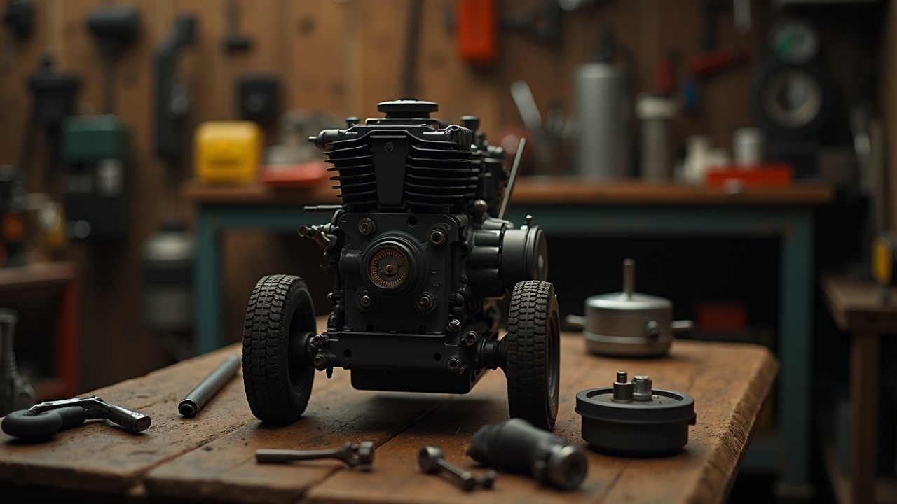
This guide covers every system in a small engine — fuel, ignition, compression, lubrication, governor, and starting — with enough depth that you can diagnose and repair any common failure using basic hand tools. No prior mechanical experience required. Every step assumes you're working in a home garage with a standard socket set, screwdrivers, and a multimeter.
Small engines power lawn mowers, tillers, generators, pressure washers, log splitters, water pumps, go-karts, and dozens of other tools. The principles are identical across all of them. Learn one, and you can fix any of them.
A Brief History
The small air-cooled engine traces back to the early 1900s. Briggs & Stratton began producing small gasoline engines in 1919. Tecumseh (now LCT) and Kohler followed. Honda entered the American market in the 1960s and raised the quality bar with overhead valve designs that ran cleaner and lasted longer. Today, most consumer small engines are manufactured by Briggs & Stratton, Honda, Kohler, Kawasaki, Subaru (Robin), and Chinese manufacturers producing under various brand names.
The fundamentals haven't changed in a century: intake, compression, power, exhaust. Air and fuel enter the cylinder. The piston compresses the mixture. A spark plug ignites it. The expanding gases push the piston down. The exhaust valve opens. Repeat.
2. Engine Types
2-Stroke vs. 4-Stroke
**2-Stroke engines** complete their power cycle in two piston strokes (one revolution). Fuel and oil are mixed together — the oil burns with the fuel, which is why 2-strokes smoke. They have no separate oil sump, no valves, and no camshaft. Ports in the cylinder wall handle intake and exhaust. They produce more power per pound but run hotter, burn dirtier, and wear faster. Common applications: chainsaws, string trimmers, leaf blowers, older outboard motors.
**4-Stroke engines** complete their power cycle in four strokes (two revolutions): intake, compression, power, exhaust. They have a dedicated oil sump, intake and exhaust valves operated by a camshaft, and run cleaner and cooler. Heavier per horsepower but significantly more fuel-efficient and longer-lasting. Common applications: lawn mowers, generators, tillers, pressure washers, pumps.
The repair principles in this guide focus on 4-stroke engines, since they dominate the equipment most people own. 2-stroke-specific notes are included where relevant.
OHV vs. Flathead (L-Head)
**Flathead (L-Head)** engines mount the valves in the block beside the cylinder, operated by a camshaft below the crankshaft. Simple, cheap, and easy to work on. Lower efficiency because the combustion chamber shape is compromised by the side-valve arrangement. Still found on budget mowers and older equipment.
**Overhead Valve (OHV)** engines mount the valves in the cylinder head above the piston. Pushrods and rocker arms transfer camshaft motion from below. Better combustion chamber shape, higher compression ratios, more power per cubic centimeter, and better fuel economy. Honda's GX series popularized this layout in small engines. Now standard on most quality equipment.
**Overhead Cam (OHC)** engines are rare in small equipment but exist on some Honda and Kawasaki commercial engines. The camshaft sits in the cylinder head itself, eliminating pushrods. Smoother operation, higher RPM capability, but more complex.
Shaft Orientation
**Vertical shaft** engines mount on top of the equipment with the crankshaft pointing down. Used on walk-behind mowers — the blade bolts directly to the crankshaft.
**Horizontal shaft** engines mount with the crankshaft parallel to the ground. Used on generators, tillers, pressure washers, pumps, go-karts, and anything that drives a belt, chain, or direct coupling.
Displacement and Power Ratings
Small engine displacement ranges from about 25cc (small 2-stroke trimmer) to 999cc (large commercial zero-turn mower). Common walk-behind mower engines run 140-190cc. Most generators and pressure washers use 200-420cc engines.
Horsepower ratings were dropped by most manufacturers in 2010 after a class-action lawsuit revealed that rated HP figures were inflated by up to 30% across the industry. Briggs & Stratton and others switched to "gross torque" ratings measured in foot-pounds. A rough conversion: 1 HP equals approximately 1.5 ft-lbs of gross torque for small engines at governed speed.
3. Fuel System
How a Carburetor Works
The carburetor is a passive device — no electronics, no computer, no fuel injection. It uses the Venturi effect: air flowing through a narrowed passage (the venturi) creates a low-pressure zone that draws fuel from a reservoir through calibrated orifices (jets).
**Key components:**
- **Float and needle valve.** A hollow float rides on the fuel level inside the float bowl. As the bowl fills, the float rises and pushes a small needle into its seat, shutting off fuel flow. When the engine consumes fuel and the level drops, the float descends, the needle unseats, and fuel flows in again. This maintains a constant fuel level — critical because jet flow rates depend on consistent fuel head pressure.
- **Main jet.** A brass orifice (typically 0.5-1.5mm diameter) that meters fuel flow at full throttle. Located at the bottom of the emulsion tube. If this jet is clogged, the engine starves at high RPM.
- **Pilot (idle) jet.** A much smaller orifice (0.3-0.7mm) that meters fuel at idle and low throttle. Extremely susceptible to clogging from ethanol varnish. A clogged pilot jet is the single most common cause of engines that won't idle or die when the choke is released.
- **Emulsion tube.** A brass tube with small holes along its length, standing vertically in the carburetor throat. Fuel rises through the main jet into the emulsion tube. Air enters through the holes. The mixture of fuel and air (an emulsion) sprays from the top of the tube into the venturi. This pre-mixing improves atomization.
- **Choke plate.** A butterfly valve upstream of the venturi that restricts airflow when closed. Restricting air increases vacuum in the venturi, pulling more fuel, creating a rich mixture for cold starting.
- **Throttle plate.** A butterfly valve downstream of the venturi that controls how much air/fuel mixture enters the engine, governing RPM.
Ethanol Damage
Ethanol (E10, E15) is the number one killer of small engine carburetors. The mechanism involves three processes:
**Phase separation.** Ethanol is hygroscopic — it absorbs water from the atmosphere. When the ethanol-water concentration in gasoline exceeds roughly 0.5% water by volume, the ethanol and water separate from the gasoline and sink to the bottom of the tank. This ethanol-water layer is corrosive, not combustible, and gets sucked into the carburetor first because fuel pickups sit at the bottom of the tank.
**Varnish formation.** Ethanol-blended fuel begins forming gummy varnish deposits within 30 days of purchase. By 60-90 days, enough varnish has formed to partially or fully clog pilot jets. The National Renewable Energy Laboratory documented accelerated oxidation and deposit formation in E10 fuels left in small engine tanks (NREL/TP-540-43543, 2008).
**Material degradation.** Ethanol attacks rubber and certain plastics. Fuel lines, primer bulbs, carburetor gaskets, and float needle tips made from non-ethanol-compatible materials swell, crack, or dissolve. Most manufacturers switched to ethanol-compatible materials after 2008, but older equipment and aftermarket parts still use vulnerable compounds.
Fuel Stabilization
**Prevention** is cheaper than carburetor rebuilds. Three strategies:
1. **Use ethanol-free fuel** (often sold as "recreation fuel" or "REC-90" at select gas stations). Costs more per gallon but eliminates phase separation, varnish, and material damage. Worth it for any equipment that sits between uses.
2. **Add fuel stabilizer** (STA-BIL, Star Tron, Sea Foam) to ethanol-blended fuel at each fill-up — not just for storage. Stabilizers contain antioxidants that slow varnish formation and corrosion inhibitors. Follow label ratios.
3. **Run carburetors dry** before storage. After the last use of the season, close the fuel valve (if equipped) and let the engine run until it dies. Then remove the float bowl drain screw and drain any remaining fuel. An empty carburetor cannot form varnish.
Carburetor Cleaning and Rebuild
**Tools needed:** 10mm socket or wrench, flat and Phillips screwdrivers, carburetor cleaner spray (Berryman B-12 Chemtool or equivalent), compressed air, thin wire (strand from a wire brush or guitar string), small container for parts.
**Step-by-step:**
1. **Remove the air filter.** Note how it's oriented for reassembly. Inspect — if it's soaked in fuel, the carburetor was flooding.
2. **Photograph the linkages.** Before disconnecting anything, take photos of the throttle linkage, choke linkage, governor spring, and fuel line connections. These are easy to misroute on reassembly.
3. **Disconnect the fuel line** and plug it (a small bolt or golf tee works). Remove throttle and choke linkages. Remove the two mounting bolts/nuts holding the carburetor to the intake manifold.
4. **Remove the float bowl.** Usually one bolt on the bottom center. Catch any fuel that drains. Inspect the bowl for debris, rust, or white powdery residue (zinc corrosion from ethanol).
5. **Remove the float and needle.** The float pivots on a pin — slide it out. The needle valve hangs from a clip on the float or sits in the needle seat. Inspect the rubber tip of the needle — if it has a groove worn into it, replace it.
6. **Remove jets.** The main jet is usually a brass screw at the bottom of the emulsion tube. The pilot jet is a smaller brass screw nearby. Use a properly-fitting screwdriver to avoid damaging the soft brass slots.
7. **Soak or spray.** Submerge metal parts in carburetor cleaner for 30 minutes, or spray each passage thoroughly. Use compressed air to blow through every orifice. Hold jets up to the light — you should see a clean, round hole. If not, push a thin wire through (never a drill bit — it will enlarge the orifice and ruin the calibration).
8. **Replace gaskets.** A rebuild kit ($5-$10) includes new gaskets, needle valve, float bowl O-ring, and sometimes a new float. Always replace gaskets — reusing old ones guarantees a fuel leak or vacuum leak.
9. **Reassemble.** Set float height per manufacturer specification (usually measured as the distance from the gasket surface to the top of the float with the carburetor inverted and the float resting on the needle). Typical float height is 12-22mm depending on the carburetor.
10. **Reinstall and test.** Reconnect fuel, linkages, and air filter. Start the engine. If it runs but hunts (surges), the pilot jet may still be partially blocked, or there is a vacuum leak at the mounting gasket.
4. Ignition System
How a Magneto Works
Small engines use a magneto ignition — no battery required for spark (except on electric-start models, where the battery runs the starter motor but the magneto still generates its own spark).
A permanent magnet is embedded in the flywheel. As the flywheel spins, the magnet passes the ignition coil (also called the ignition module or armature), which is mounted to the engine block with a small air gap (typically 0.008-0.012 inches). The moving magnetic field induces a current in the primary winding of the coil. When the field collapses as the magnet passes, the sudden change induces a high-voltage spike in the secondary winding — typically 15,000-25,000 volts — which fires the spark plug.
**Electronic ignition** (standard since the 1980s) uses a solid-state module to control spark timing. No moving contacts, no adjustment needed, and the module either works or it doesn't. Failures are rare but not repairable — replace the entire module ($15-$40).
**Points ignition** (pre-1980s engines) uses mechanical contact points that open and close to interrupt the primary circuit. Points wear, pit, and go out of adjustment. If you're working on an old engine with points, check the gap (typically 0.020 inches) and inspect for pitting or erosion. Filing points is a temporary fix — replace them.
Setting the Air Gap
The distance between the ignition coil legs and the flywheel magnets is critical. Too wide and the spark weakens. Too narrow and the coil can strike the flywheel.
1. Remove the spark plug wire. 2. Rotate the flywheel until the magnets align with the coil legs. 3. Loosen the coil mounting screws. 4. Insert a feeler gauge or business card (0.010-0.012" for most engines) between the coil legs and the flywheel magnets. 5. The magnets will pull the coil snug against the gauge. 6. Tighten the mounting screws. 7. Remove the gauge and rotate the flywheel by hand to verify clearance.
Spark Plug Reading
The spark plug is a diagnostic window into combustion. Pull the plug and read the electrode color:
``` SPARK PLUG COLOR CHART -------------------------------------------------- Color/Condition | Diagnosis -------------------------------------------------- Light tan / gray | Normal combustion. Correct | air/fuel mixture. -------------------------------------------------- White / blistered | Running lean (too much air, | not enough fuel). Check for | air leaks, clogged fuel | line, dirty fuel filter. -------------------------------------------------- Black, dry soot | Running rich (too much | fuel). Choke stuck closed, | dirty air filter, float | level too high. -------------------------------------------------- Black, wet/oily | Oil burning. Worn rings, | worn valve seals, or | engine tilted wrong way | during use/storage. -------------------------------------------------- Rust-brown deposits | Coolant leak into | combustion chamber (liquid- | cooled engines only). -------------------------------------------------- Electrode eroded/melted | Severe overheating. Check | cooling fins, timing, | lean mixture. -------------------------------------------------- ```
**Spark plug replacement:** Use the manufacturer-specified plug (typically Champion or NGK, specific model stamped on the plug or listed in the manual). Gap to specification using a wire-type gauge (not coin-type — too imprecise). Common gap range: 0.028-0.032 inches. Tighten to 15 ft-lbs or finger-tight plus 1/4 turn.
Kill Switch Circuit
The kill switch (also called the bail lever, operator presence control, or dead man's lever on mowers) works by grounding the primary winding of the ignition coil. When grounded, no voltage can build, and no spark occurs.
If an engine won't spark, disconnect the kill switch wire from the coil and test again. If spark returns, the problem is a shorted kill switch wire (rubbed through insulation, corroded connector, or a stuck switch). This is one of the most commonly overlooked causes of "no spark."
5. Compression
An engine needs compression to run. Minimum cranking compression for most small engines is 60-90 PSI. A healthy engine typically reads 90-150 PSI depending on design.
Compression Testing
1. Remove the spark plug. 2. Thread a compression gauge into the spark plug hole. 3. Open the throttle fully (this opens the intake valve on some carburetors). 4. Pull the starter rope or crank the electric starter 4-6 pulls. 5. Read the gauge. It should climb with each pull and stabilize.
**Below 60 PSI:** Engine won't run. Indicates significant internal wear or damage.
Leak-Down Testing
A leak-down test pinpoints where compression is escaping. It requires a leak-down tester (pressurized air applied to the cylinder through the spark plug hole with the piston at top dead center).
1. Set the piston at TDC on the compression stroke (both valves closed). 2. Apply regulated air pressure (typically 100 PSI). 3. Read the percentage of leakage on the gauge. 4. **Listen for where the air escapes:** - Air hissing from the carburetor/intake = leaking intake valve - Air hissing from the muffler/exhaust = leaking exhaust valve - Air hissing from the oil fill or dipstick tube = worn piston rings - Bubbles in the cooling system (liquid-cooled) = blown head gasket
**Acceptable leakage:** Under 15% is healthy. 15-25% is worn but serviceable. Over 25% needs attention.
Valve Adjustment
OHV engines require periodic valve clearance (lash) adjustment. Over time, valve seats wear and the effective clearance changes. Too tight and the valve doesn't fully close (compression loss, burnt valves). Too loose and the engine is noisy with reduced valve lift.
1. Remove the valve cover. 2. Rotate the engine to TDC on the compression stroke (both valves closed — both rocker arms loose). 3. Use a feeler gauge between the rocker arm and valve stem tip. 4. Typical clearance: intake 0.003-0.005", exhaust 0.005-0.007" (always check manufacturer specs). 5. Adjust by loosening the locknut, turning the adjustment screw, and retightening.
Head Gasket Diagnosis
Symptoms of a blown head gasket on an air-cooled small engine:
- Low or inconsistent compression
- Oil in unexpected places (on top of the piston, in the air filter)
- Engine overheating
- Loss of power
- White smoke from exhaust (burning oil that leaked past the gasket)
Remove the cylinder head and inspect the gasket. Look for burn-through, erosion channels, or crushed areas. Always replace the head gasket with a new one — never reuse. Torque the head bolts to specification in the correct sequence (typically a cross pattern).
Ring Wear Signs
- Blue/white smoke from the exhaust, especially on startup or under load
- Excessive oil consumption
- Oil fouling of spark plug (black, wet deposits)
- Low compression that improves when a tablespoon of oil is squirted into the cylinder ("wet compression test")
Ring replacement requires splitting the crankcase or removing the cylinder. On most small engines, by the time rings are worn enough to cause symptoms, the cylinder bore is also worn and may need honing or oversizing.
6. Lubrication
Splash vs. Pressure Lubrication
**Splash lubrication** is the most common system in small engines. A dipper or slinger attached to the connecting rod dips into the oil sump on each revolution, flinging oil onto the cylinder walls, bearings, and other surfaces. Simple, no oil pump, no oil filter on most models. The downside: oil level is critical. Too low and the dipper can't reach. Too high and the crankcase pressurizes, pushing oil past seals.
**Pressure lubrication** uses a gear-driven oil pump to force oil through drilled passages to the main bearings, rod bearings, and cam bearings. Found on larger or commercial-grade engines (Kohler Command, Kawasaki FX series, most V-twin engines). These engines usually have an oil filter.
Oil Selection
Most small engine manufacturers specify SAE 30 for temperatures above 40°F and 5W-30 or 10W-30 for colder conditions. Synthetic oils are acceptable and offer better high-temperature stability and cold-flow characteristics.
**Do not use automotive oil with friction modifiers or energy-conserving additives** in small engines with wet clutches (rare, but some generators and multi-function units). These additives cause clutch slippage.
For 2-stroke engines, use only TC-W3 rated 2-stroke oil (for water-cooled applications) or JASO FC rated oil (for air-cooled). Never use automotive oil in a 2-stroke — it doesn't burn cleanly and will carbon-foul the exhaust port and spark arrestor.
Checking and Changing Oil
**Check oil** with the engine on a level surface, dipstick wiped clean, reinserted without threading, and pulled out to read the level. Oil should be between the hash marks. Color tells you condition: honey/amber is fresh, dark brown is used but acceptable, black and gritty means change immediately, milky/gray indicates water contamination.
**Change interval:** Every 25-50 hours of operation or once per season, whichever comes first. New engines should have their oil changed after the first 5 hours (break-in oil contains metal particles from initial wear).
**Oil change procedure:**
1. Run the engine for 2-3 minutes to warm the oil (warm oil drains faster and carries more contaminants). 2. Stop the engine. Disconnect the spark plug wire. 3. Place a drain pan under the engine. 4. Remove the drain plug (bottom of the engine) or tip the mower on its side (carburetor side UP to prevent oil flooding the air filter). 5. Allow to drain completely. 6. Replace the drain plug. Fill with the specified amount of new oil (typically 18-20 oz for a walk-behind mower engine). 7. Check level with dipstick. Do not overfill.
Low-Oil Shutdown
Most modern small engines include an oil level sensor (Oil Guard, Oil Alert, Oil Sentry — various brand names). A float switch or pressure sensor in the oil sump kills the ignition circuit when oil drops below the safe level.
This system saves engines from catastrophic bearing failure, but it also causes confusion. An engine that shuts off immediately after starting, or won't start at all, may simply be low on oil. Check the oil level first before diving into carburetor or ignition diagnosis. On uneven ground, a full oil sump can trigger the sensor falsely — level the equipment and try again.
7. Governor System
Mechanical Governor Operation
The governor maintains a constant engine speed under varying loads. Without it, the engine would slow down when the mower hits thick grass and over-rev when the load lightens.
A mechanical governor uses centrifugal weights inside the crankcase, driven by the camshaft gear. As engine speed increases, the weights swing outward, pushing a spool or lever that acts on an external governor shaft. The governor shaft connects to the throttle via a linkage. A governor spring pulls the throttle toward open; the governor mechanism pushes it toward closed. The engine runs at the speed where these two forces balance.
**Speed adjustment:** Governed speed is set by spring tension. Moving the governor spring to a different hole on the governor lever (or adjusting the tension screw on some models) changes the target RPM. Most consumer mowers are governed to 3,000-3,200 RPM. Generators must hold 3,600 RPM precisely (for 60 Hz output).
Never exceed the manufacturer's maximum governed speed. Over-revving causes valve float, bearing damage, and can throw the blade on a mower.
Governor Hunting and Surging
**Hunting** (rhythmic surging where the engine speeds up and slows down repeatedly) is one of the most common small engine complaints. Causes:
1. **Clogged pilot jet.** The engine starves at idle/low speed, drops RPM, the governor opens the throttle, RPM climbs, the engine runs fine at higher RPM, the governor closes the throttle, and the cycle repeats. Clean the carburetor — specifically the pilot circuit.
2. **Governor linkage binding.** Bent linkage, corrosion, or lack of lubrication prevents smooth throttle movement. The governor overcorrects with each adjustment. Clean and lubricate all pivot points. Straighten bent links.
3. **Governor spring stretched or wrong hole.** A weak or misplaced spring changes the balance point. Verify spring placement against the service manual.
4. **Vacuum leak.** An air leak at the carburetor mounting gasket or intake manifold allows unmetered air in, leaning the mixture unpredictably. Replace gaskets. Check for cracked intake boots.
Static Governor Adjustment
If the governor was disassembled or the governor shaft was moved:
1. Loosen the clamp bolt on the governor lever (external). 2. Rotate the governor shaft fully in the direction that opens the throttle (push the throttle linkage to wide open). 3. While holding the shaft, tighten the clamp bolt. 4. Start the engine and verify governed speed with a tachometer. Adjust the governor spring if needed.
8. Starting System
Recoil Starter Repair
The recoil (pull) starter is a spring-loaded rope mechanism. You pull the rope, it spins the engine, the spring retracts the rope. Failures include broken rope, broken recoil spring, worn pawls (the dogs that engage the flywheel), and tangled rope.
**Rope replacement:**
1. Remove the starter housing (3-5 bolts on the engine shroud). 2. Pull any remaining rope out and note how it's routed. 3. Remove the rope handle and untie the knot. 4. If the recoil spring is intact, wind the pulley against the spring (typically 3-5 turns, depending on the engine — check the manual) to preload it. 5. Hold the pulley, thread new rope through the hole, tie a knot inside the pulley, route through the housing, and attach the handle. 6. Slowly release the pulley to let the spring retract the rope. It should pull the handle snug against the housing with about 6 inches of rope still able to be pulled before the pulley bottoms out.
**Recoil spring replacement:** The spring is under tension and will uncoil violently if released uncontrolled. Wear eye protection. Keep the spring captive in the housing until the new spring is seated. Many replacement springs come pre-wound in a retainer cage that drops into the housing.
Electric Starter
Larger engines and generators often include electric starters. The system includes: battery (usually 12V), ignition switch or key, starter solenoid (a high-current relay), and starter motor.
**Starter motor won't engage:**
1. Check the battery voltage. Below 12.4V, charge it. Below 11.8V, the battery may be sulfated and need replacement. 2. Check the solenoid. With a multimeter, test for 12V at the solenoid input terminal when the key/button is engaged. If 12V is present but the solenoid doesn't click, replace the solenoid. 3. If the solenoid clicks but the starter doesn't spin, test for voltage at the starter motor terminal. If voltage is present, the starter motor is bad. 4. If the starter spins but doesn't engage the flywheel, the Bendix gear (the small gear that slides out to mesh with the flywheel ring gear) is stuck or worn. Clean or replace.
Solenoid Testing
Use a multimeter set to continuity:
1. Disconnect the battery. 2. Test across the two large terminals — should read open (no continuity). 3. Apply 12V to the small activation terminals — the solenoid should click and continuity should appear across the large terminals. 4. If it doesn't click: bad solenoid coil. If it clicks but no continuity: burnt contacts inside the solenoid.
Flywheel Key
The flywheel key is a small, soft metal key (usually aluminum or a zinc alloy) that indexes the flywheel to the crankshaft. Its purpose is twofold: it ensures correct ignition timing alignment, and it acts as a shear pin to protect the crankshaft if the blade strikes a solid object.
A **sheared flywheel key** shifts ignition timing, causing hard starting, backfiring through the carburetor, or no-start conditions. This is extremely common after hitting a stump, rock, or landscape edging with a mower blade.
**Diagnosis:** Remove the flywheel (requires a flywheel puller on most engines — do not hammer the crankshaft) and inspect the key. Even a partially sheared key (half-moon shape still present but shifted) will cause timing problems.
**Replace with the correct key material.** Do not substitute a steel key — it defeats the shear-pin protection and can crack the crankshaft on the next blade strike.
9. Common Repairs
Won't Start — Diagnostic Flowchart
``` ENGINE WON'T START │ ├─ Does the engine turn over (crank)? │ │ │ ├─ NO → Is the blade/output shaft obstructed? │ │ │ │ │ ├─ YES → Clear obstruction. Try again. │ │ │ │ │ └─ NO → Check recoil starter for broken rope │ │ or jammed mechanism. │ │ │ │ │ └─ Starter OK → Check for seized │ │ engine (pull plug, try to turn │ │ flywheel by hand). If seized: │ │ remove spark plug, add penetrating │ │ oil to cylinder, wait 24 hours. │ │ │ └─ YES → Engine cranks but won't fire. │ │ │ ├─ CHECK SPARK │ │ Pull plug, ground electrode against │ │ engine block, crank engine, look for │ │ blue spark. │ │ │ │ │ ├─ NO SPARK │ │ │ │ │ │ │ ├─ Disconnect kill switch wire │ │ │ │ from coil. Test again. │ │ │ │ │ │ │ │ │ ├─ Spark returns → Kill switch │ │ │ │ │ or wire is shorted. Trace │ │ │ │ │ and repair the wire. │ │ │ │ │ │ │ │ │ └─ Still no spark → │ │ │ │ Check coil air gap (0.010"). │ │ │ │ Check flywheel key (sheared?). │ │ │ │ Replace ignition coil. │ │ │ │ │ │ │ └─ Is the plug wet with fuel? │ │ │ │ │ │ │ ├─ YES → Flooded. Install dry │ │ │ │ plug, crank with throttle │ │ │ │ wide open, no choke. │ │ │ │ │ │ │ └─ NO → Fuel not reaching │ │ │ cylinder. See FUEL CHECK. │ │ │ │ │ └─ SPARK OK → Fuel or compression issue. │ │ │ ├─ CHECK FUEL │ │ │ │ │ ├─ Is there fresh fuel in the tank? │ │ │ (Fuel over 90 days old = stale.) │ │ │ │ │ │ │ ├─ NO → Add fresh fuel. Try again. │ │ │ │ │ │ │ └─ YES → Is fuel reaching the carb? │ │ │ Disconnect fuel line at carb. │ │ │ Fuel should flow freely. │ │ │ │ │ │ │ ├─ NO FLOW → Clogged fuel filter, │ │ │ │ clogged fuel cap vent (loosen │ │ │ │ cap and try), blocked fuel │ │ │ │ line, stuck fuel shutoff valve. │ │ │ │ │ │ │ └─ FUEL FLOWS → Carburetor is │ │ │ clogged. Remove and clean. │ │ │ (See Section 3.) │ │ │ │ │ └─ After carb cleaning, still won't │ │ start? → Check compression. │ │ │ └─ CHECK COMPRESSION │ Pull the starter rope. You should feel │ strong resistance on the compression │ stroke. │ │ │ ├─ NO RESISTANCE → Valve stuck open, │ │ blown head gasket, or broken │ │ connecting rod. Remove head and │ │ inspect. │ │ │ └─ COMPRESSION FEELS NORMAL → │ Do a wet compression test (add oil │ to cylinder). If compression rises │ significantly, rings are worn. If │ no change, valve sealing issue. │ Adjust valves (Section 5). ```
Runs Rough or Dies Under Load
1. **Dirty air filter.** A clogged filter starves the engine of air, creating a rich condition. Clean or replace. 2. **Partially clogged carburetor.** The main jet may be partially blocked, providing enough fuel for idle but not full throttle. 3. **Stale fuel.** Fuel with phase-separated ethanol runs poorly. Drain and replace. 4. **Intake gasket leak.** An air leak creates a lean condition. Spray carburetor cleaner around the intake gasket with the engine running — if RPM changes, the gasket leaks. 5. **Worn spark plug.** Worn electrode increases the required firing voltage. Replace the plug. 6. **Valve lash out of specification.** Re-adjust per Section 5.
Overheating
Air-cooled engines rely on cooling fins and airflow from the flywheel fan. Overheating causes:
1. **Clogged cooling fins.** Grass clippings, dirt, and debris pack between the fins and insulate the cylinder. Clean them — this is the most common cause. 2. **Missing or damaged engine shroud.** The shroud directs flywheel fan air over the fins. Without it, cooling is inadequate. 3. **Running lean.** A lean mixture burns hotter. Check for air leaks and fuel delivery. 4. **Low oil.** Oil carries heat away from internal components. Check and fill. 5. **Carbon buildup in combustion chamber.** Heavy carbon deposits cause hot spots and pre-ignition. Remove the head and scrape carbon from the piston crown and head.
Excessive Vibration
1. **Bent crankshaft.** After hitting a solid object with a mower blade, the crankshaft may bend. Remove the blade and spin the shaft — if the shaft end wobbles, it's bent. Replacement is usually more economical than straightening. 2. **Unbalanced blade.** A blade sharpened unevenly or with a chunk missing will vibrate. Balance the blade on a nail through the center hole — it should sit level. 3. **Loose mounting bolts.** Check all engine-to-deck and blade-to-shaft fasteners. 4. **Worn flywheel key.** A partially sheared key changes timing and causes uneven power pulses.
Oil Leaks
1. **Valve cover gasket.** Most common leak point. Remove, clean surfaces, replace gasket, tighten evenly. 2. **Oil sump gasket.** Requires disassembly. Use new gasket and proper sealant. 3. **Crankshaft seals.** Oil leaking from the PTO (power take-off) end or flywheel end indicates worn crankshaft seals. Requires pulling the flywheel or removing the PTO assembly to access. 4. **Breather tube.** A clogged crankcase breather (reed valve on OHV engines) builds internal pressure that forces oil past seals and gaskets. Clean or replace the breather. 5. **Overfilled oil.** Too much oil causes crankcase pressurization and forces oil out everywhere. Drain to the correct level.
10. Seasonal Maintenance
Winterization (End of Season)
Proper storage prevents 90% of spring startup failures.
**Fuel system — choose one method:**
- **Drain method.** Run the engine until it dies from fuel starvation. Remove the float bowl and drain remaining fuel. Leave the fuel tank empty. This prevents all ethanol damage.
- **Stabilize method.** Add fuel stabilizer to a full tank of fresh fuel. Run the engine for 5 minutes to circulate stabilized fuel through the carburetor. Leave the tank full (a full tank reduces condensation). Less thorough than draining but more convenient.
**Oil:** Change the oil at the end of the season, not the beginning. Used oil contains acids and combustion byproducts that corrode bearings during storage. Fresh oil protects.
**Spark plug:** Remove, inspect, clean or replace. Apply a small amount of oil into the cylinder through the plug hole and pull the starter slowly a few times to coat the cylinder walls. Reinstall the plug loosely (finger-tight — no wrench).
**Battery (if equipped):** Remove and store indoors. Attach a trickle charger or maintainer. Lead-acid batteries lose 1% charge per day in cold weather and can freeze if discharged (a fully charged battery freezes at -92°F; a 50% discharged battery freezes at -10°F).
**Exterior:** Clean all grass, dirt, and debris from the engine, deck, and undercarriage. Touch up any bare metal with spray paint to prevent rust. Lightly oil any exposed metal linkages or pivot points.
**Storage location:** A dry, covered area. If storing a mower in an unheated shed, the temperature swings are fine — moisture is the enemy, not cold.
Spring Startup
1. Check oil level and condition. If you changed oil in the fall, it should be clean. If not, change it now. 2. Install a fresh spark plug or verify the existing one. 3. Check the air filter. 4. If fuel was stabilized, it should still be good for up to 12 months (depending on stabilizer brand). If the tank was drained, add fresh fuel. 5. For mowers: sharpen or replace the blade. Inspect the blade adapter and flywheel key. 6. Check tire pressure (if applicable). 7. Prime the carburetor (3-4 presses on the primer bulb, or set choke to full). 8. Start the engine. Let it warm up for 1-2 minutes before applying load.
Storage Preparation for Extended Downtime
For equipment stored longer than 6 months:
- Follow all winterization steps.
- Fog the cylinder with fogging oil (spray into the spark plug hole and carburetor intake while cranking slowly).
- Seal the exhaust and air filter openings with plastic and a rubber band to prevent moisture and insect intrusion (mud dauber wasps commonly nest in mufflers and air intake passages, blocking airflow).
- Place a moisture-absorbing desiccant packet near the engine if stored in a humid environment.
- For generators and pressure washers: run the pump dry or add pump saver (antifreeze lubricant) through the water connections.
11. Sources
1. Briggs & Stratton, "Single Cylinder OHV Repair Manual," MS-4015, 2020. 2. Briggs & Stratton Service Bulletin SE-1017, "Ethanol Fuel Effects on Small Engines," 2019. 3. Honda Motor Co., "GX Series Technical Manual," 2021. 4. Kohler Engines, "Service Manual for Command PRO Series," TP-2503-B, 2019. 5. National Renewable Energy Laboratory, "Effects of Intermediate Ethanol Blends on Legacy Vehicles and Small Non-Road Engines," NREL/TP-540-43543, 2008. 6. Dempsey, Paul, "Small Gas Engine Repair," 4th Edition, McGraw-Hill, 2008. 7. Society of Automotive Engineers, "SAE J1940: Small Engine Power and Torque Rating Procedure," 2011. 8. Equipment & Engine Training Council (EETC), "Fundamentals of Small Engine Repair," certification curriculum, 2020. 9. Tecumseh Products Company, "Technician's Handbook," Form No. 692509, 2007. 10. Kawasaki Engines, "FX Series Technical Service Manual," 2018.
`[practical-skills]` `[beginner]`