plants
Timber Frame Construction
Timber Frame Construction - comprehensive guide from Nored Farms.
title: "Timber Frame Construction" subtitle: "Mortise, Tenon, and the Engineering of Structures That Outlast Centuries" author: "Nored Farms" date: "2026"
Content Extraction Summary
Hook Options
1. Steel-framed buildings collapse in under 30 minutes at 1000degF because steel loses 50% of its yield strength at 593degC. A timber frame chars at a predictable 1.5 inches per hour, maintaining full structural capacity behind the char layer — which is why timber-framed buildings regularly survive fires that buckle steel (Buchanan, 2001). 2. A properly cut mortise-and-tenon joint has been holding buildings together for at least 7,000 years — the oldest known example is a well lining near Leipzig, Germany, dated to 5000 BCE (Tegel et al., 2012). The joint works because wood loaded in compression perpendicular to grain deforms plastically before failing, giving warning instead of catastrophic collapse. 3. Most people assume timber framing died because stick framing is stronger. Stick framing won because it requires less skill, not more strength. A 2x4 wall is an assembly of interchangeable parts any laborer can nail together. A timber frame is a machine — every joint is custom-fitted, and the structure relies on geometry rather than fastener count.
Key Mechanism
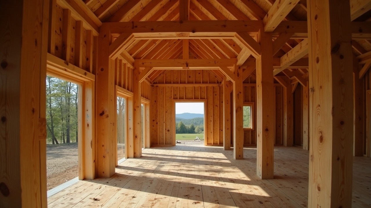
Timber frames transfer loads through large-section members joined by interlocking wood joinery — primarily mortise-and-tenon connections secured with hardwood pegs. The structure works as a series of rigid bents (cross-frames) connected by longitudinal beams. Because the members are large (typically 6x6 minimum for posts, 6x8 or 8x8 for beams), they have inherent fire resistance: wood chars at approximately 0.6 inches per 10 minutes, but the char layer insulates the remaining cross-section, preserving structural integrity. The joints distribute load through bearing surfaces rather than through fasteners, making the connections stronger in compression than the wood itself.
Misconception to Correct
"Timber framing is just heavy stick framing" or "post and beam is the same as timber frame." These are different structural systems. Stick framing uses dimensional lumber (2x4 to 2x12) fastened with nails and relies on plywood sheathing for racking resistance. Post-and-beam uses large timbers but connects them with metal hardware (brackets, bolts, straps). Timber framing uses traditional joinery — mortise-and-tenon, dovetails, scarf joints — secured with wooden pegs. The joints themselves resist racking through knee braces and the mechanical interlock of the joinery. No metal in the structural frame.
Practical Application
A competent owner-builder can design and raise a simple timber frame bent (two posts, a tie beam, and rafters with knee braces) using hand tools and green local hardwood. A 16x24-foot single-story frame requires roughly 2,500 board feet of timber, can be raised by 8-12 people in a day, and enclosed with SIPs for a high-performance building envelope. Total material cost for the frame alone runs $3,000-8,000 depending on species and whether you mill your own lumber.
Citation-Ready Claims
- Wood chars at approximately 0.6 in per 10 minutes (1.5 in/hr) under standard fire exposure — (Buchanan, 2001, *Structural Design for Fire Safety*, Wiley)
- Steel loses 50% yield strength at 593degC (1100degF), reaching failure in typical building fires within 15-30 minutes without fireproofing — (AISC, *Steel Construction Manual*, 15th Ed.)
- Oldest known mortise-and-tenon joints dated to ~5000 BCE from well linings near Leipzig, Germany — (Tegel et al., 2012, *PLOS ONE*, 7(12), e51374)
- Douglas fir allowable bending stress (Fb) of 1,350 psi for Select Structural grade — (NDS, *National Design Specification for Wood Construction*, AWC, 2018)
- White oak compression perpendicular to grain: 800 psi allowable — (Wood Handbook, FPL-GTR-282, USDA Forest Products Laboratory, 2021)
- Green timber moisture content typically 30-80% depending on species; air-drying to 19% requires 1 year per inch of thickness for hardwoods — (Simpson, 1991, *Dry Kiln Operator's Manual*, USDA)
- SIP R-values of R-24 to R-48 depending on thickness (4.5 to 12.25 inches) — (SIPA, Structural Insulated Panel Association technical specifications)
1. Introduction — Why Timber Frames Stand When Other Structures Fall
Steel loses half its strength at 1100degF. A steel I-beam in an unprotected structure can buckle in under 30 minutes during a building fire (AISC, *Steel Construction Manual*). This is not theoretical — it is the primary reason steel-framed commercial buildings require expensive spray-on fireproofing.
A timber frame does something counterintuitive. It chars.
Wood exposed to fire develops a char layer at a predictable rate of approximately 1.5 inches per hour (Buchanan, 2001). That char layer is almost pure carbon — a poor conductor of heat. It insulates the wood behind it, slowing further charring and preserving the structural cross-section. An 8x8 oak post in a fire still has a 5x5 intact core after one hour. That core retains its full compressive strength. The beam does not buckle, does not twist, does not suddenly lose capacity the way steel does above its critical temperature. This is why fire codes in many jurisdictions classify heavy timber (members 6 inches or larger in minimum dimension) as Type IV construction — the same fire-resistance category that requires sprinklers and fire-rated assemblies in other material types, achieved here by the physics of the material itself.
**Timber framing vs. stick framing.** Modern residential construction in North America runs almost entirely on stick framing — 2x4 and 2x6 wall studs placed 16 inches on center, sheathed with plywood or OSB for racking resistance, held together by thousands of nails. This system dominates because it is fast, requires minimal skill, and uses commodity lumber that arrives at the job site pre-dimensioned.
Timber framing is the older system. The structural skeleton consists of large-section members — posts, beams, rafters, braces — joined by interlocking wood joints rather than metal fasteners. The joints transfer load through bearing surfaces. A mortise-and-tenon connection does not rely on the shear strength of a nail or bolt. It relies on the compressive strength of wood against wood, locked in place by a hardwood peg that prevents the joint from pulling apart.
**Post-and-beam is not timber framing.** Post-and-beam construction uses large timbers but joins them with metal brackets, through-bolts, and engineered connectors. The visual result is similar. The structural behavior is different. Metal connectors concentrate stress at bolt holes. Traditional joinery distributes stress across the full bearing surface of the joint. Post-and-beam is faster to build. Timber framing is stronger at the connections and ages better because there is no metal to corrode.
The oldest surviving timber frames in Europe — the stave churches of Norway, the cruck frames of England — are 800 to 1,000 years old. The mortise-and-tenon joint itself dates to at least 5000 BCE, documented in well linings excavated near Leipzig, Germany (Tegel et al., 2012). The structural principle has not changed because it does not need to. Wood in compression does not fatigue. A properly designed timber joint, kept dry, has no theoretical lifespan limit.
2. Wood Selection — Species, Moisture, and Why Green Timber Is Not a Shortcut
The species you choose determines the strength, workability, weight, and cost of every joint you cut. Timber framing uses species in ways that matter more than in stick framing because the members are larger, the joints are tighter, and the consequences of poor material selection compound over decades.
Species Selection
| Species | Density (lb/ft3, air-dried) | Fb Bending Stress (psi) | Fc Compression Parallel (psi) | Fc-perp Compression Perpendicular (psi) | Workability | Cost (per BF, rough-sawn) | Best Use | |---|---|---|---|---|---|---|---| | White oak | 47 | 1,200 | 1,100 | 800 | Moderate — hard, checks if dried fast | $3.50–6.00 | Posts, sills, any ground-contact risk | | Red oak | 44 | 1,100 | 1,000 | 700 | Moderate — open pores, not rot-resistant | $2.50–4.50 | Interior beams, tie beams | | Douglas fir | 34 | 1,350 | 1,350 | 625 | Excellent — straight grain, takes tools well | $2.00–4.00 | Rafters, purlins, long spans | | Eastern white pine | 25 | 875 | 725 | 350 | Easy — soft, light, easy to cut | $1.50–3.00 | Plates, purlins, infill framing | | Eastern hemlock | 28 | 850 | 800 | 400 | Good — moderate hardness, stable | $1.50–2.50 | Posts, beams, general framing | | Western red cedar | 23 | 750 | 650 | 350 | Easy — soft, highly rot-resistant | $4.00–7.00 | Sills, exterior exposure only |
**White oak** is the gold standard for timber framing in the eastern United States. Tyloses — cellular growths that block the pore structure — make white oak naturally resistant to rot and insect damage. Its compression-perpendicular value of 800 psi means joints bear heavy loads without crushing. The trade-off is weight (a 12-foot 8x8 white oak beam weighs roughly 250 pounds) and a tendency to check (surface crack) if dried too quickly.
**Douglas fir** dominates western timber framing for good reason. It has the highest bending strength on this list — 1,350 psi in Select Structural grade (NDS, 2018). It grows straight, machines cleanly, and weighs 30% less than oak. For roof systems where bending strength matters more than compression perpendicular, Douglas fir is the rational choice.
**Eastern white pine** is the lightest and easiest to work but structurally the weakest. Use it for plates (horizontal members that sit on top of posts and carry no bending load) and purlins in lightly loaded roof systems. Do not use it for tie beams, major posts, or any member that sees significant bending stress.
Green Timber vs. Kiln-Dried
Green timber has a moisture content (MC) of 30–80% depending on species and season of harvest. Kiln-dried timber is brought to 12–19% MC. Air-dried timber reaches roughly 12–15% MC at equilibrium in most climates.
Most traditional timber frames are cut green. There are good reasons for this:
- **Green wood cuts easier.** A sharp chisel through green oak requires roughly half the force of the same cut in dry oak. Mortising is faster. Layout marks scribe cleaner.
- **Green wood is cheaper.** Kiln-drying large timbers (8x8 and above) is expensive, slow, and limited to a few specialty kilns. Air-drying takes 1 year per inch of thickness for hardwoods (Simpson, 1991). An 8x8 white oak beam needs 4 years to air-dry to 19% MC.
- **The frame tightens as it dries.** Tenons shrink inside mortises, and drawbore pegs pull the joint tighter as moisture leaves the wood. This is by design — traditional joinery accounts for shrinkage.
The trade-offs of green timber are real:
- **Checking.** Surface cracks form as the outer shell dries faster than the core. Checks are cosmetic in large timbers — they do not reduce structural capacity because they follow grain lines and do not cross critical sections.
- **Shrinkage.** Wood shrinks tangentially (across the growth rings) at roughly twice the rate it shrinks radially. An 8x8 green post can shrink to 7.5 x 7.75 inches as it reaches equilibrium MC. Joint dimensions must account for this.
- **Twist and bow.** Timbers with spiral grain or off-center pith will move as they dry. Select timbers with the pith close to center and grain as straight as possible.
Grading
Timber for framing should be graded visually. Key defects to reject:
- **Pith visible on more than one face.** The pith (center of the tree) is the weakest point and will check heavily.
- **Knots larger than 1/3 the face width** on a bending member. Knots in compression members matter less.
- **Slope of grain exceeding 1:12** on bending members (1:8 for compression-only posts). Grain deviation reduces bending strength proportionally.
- **Ring shake.** Separation along a growth ring — indicates internal stress and potential structural failure under load.
- **Wane** (bark or missing wood on edges) on bearing surfaces. Wane on non-bearing faces is acceptable.
3. Tools — Traditional and Power
Timber framing was done for millennia with hand tools. It can still be done that way, and many framers prefer it for one- and two-person operations where the rhythm of hand work matters more than speed.
Essential Hand Tools
**Framing chisels (1-inch, 1.5-inch, 2-inch).** Beveled-edge timber framing chisels are longer and heavier than bench chisels — typically 14–16 inches overall with socket handles built to take mallet blows. Use the 1.5-inch for most mortise work; the 2-inch for cleaning large housings. Budget: $40–80 per chisel (Barr, MHG, Narex).
**Commander mallet.** A heavy wooden mallet (3–5 lb head) for driving framing chisels. Lignum vitae or dogwood head, hickory handle. Do not use a steel hammer on chisel handles — it mushrooms the steel and transfers shock poorly. Budget: $30–60.
**Slick.** A slick is a giant chisel — 3 to 4 inches wide, 24–30 inches long — pushed by hand, never struck. Used for paring tenon cheeks, cleaning housing bottoms, and trimming end grain. The slick is the precision tool in a framer's kit. A sharp slick can take shavings as thin as a plane. Budget: $100–250 for a quality used slick; new slicks from specialty makers run $200–500.
**Auger (brace and bit or hand-crank).** For boring peg holes and clearing mortise waste. A 1-inch or 1.5-inch auger bit in a heavy-duty brace (14-inch sweep) removes material faster than chopping from solid. Bore overlapping holes in the mortise waste area, then clean up walls with a chisel. Budget: $60–120 for a quality brace-and-bit set.
**Drawknife.** For chamfering edges, removing bark, and shaping. A 10-inch blade is the standard size. Budget: $40–80.
**Timber framing square.** Not a standard carpenter's square. A timber framing square (also called a steel square for layout) has a 24-inch blade and 16-inch tongue, marked with rafter tables, board-feet scales, and octagon layout scales. The traditional layout tool for all rafter cuts. Budget: $30–60.
Power Tools
**Chain mortiser.** The single tool that most transforms production speed. A chain mortiser cuts a clean, square-bottomed mortise in 30–60 seconds — work that takes 15–30 minutes by hand. Mafell and Makita make dedicated chain mortisers. Budget: $1,500–3,500. Justified if you are cutting more than 30 mortises.
**Beam drill.** A right-angle drill with a 1-inch or 1.5-inch auger bit, designed for boring perpendicular holes in large timbers. The Milwaukee Hole Hawg is the industry standard. Budget: $200–350.
**Circular saw (16-inch worm-drive or beam saw).** A 16-inch Makita beam saw cuts through an 8x8 in a single pass. A standard 7.25-inch circular saw requires cuts from two sides and does not reliably meet in the middle without a guide. Budget: beam saw $700–1,000; standard circular $150–250.
**Router (3.25 HP plunge).** For housing joints (shallow recesses where one timber sits into another). A router with a straight bit cleans housing seats faster and flatter than a chisel. Budget: $200–350.
Sharpening
A dull chisel is a dangerous tool — it requires more force, slips off the cut, and bruises the wood instead of shearing it. Timber framing chisels should be sharpened every 20–30 minutes of active cutting.
- **Primary bevel:** 25 degrees, ground on a bench grinder or coarse stone (220 grit)
- **Secondary (micro) bevel:** 30 degrees, honed on 1000-grit and polished on 4000–6000-grit waterstone
- **Back flat:** The back of the chisel must be dead flat for paring. Lap the back on a flat stone until the first 1/2 inch is mirror-polished.
A sharp chisel, pushed straight into green oak end grain, should sever fibers cleanly with no tearing. If you see torn grain, the edge is not sharp.
4. Joinery — The Structural Language of Timber Framing
Every connection in a timber frame is a joint designed to resist a specific set of forces. Choosing the wrong joint for a given location is a structural error, not a cosmetic one. This section covers the primary joints, their load characteristics, and where each belongs in a frame.
Mortise and Tenon
The foundation of the system. A mortise is a rectangular hole cut into one timber; a tenon is the tongue cut on the end of the mating timber, shaped to fit the mortise. The joint transfers load through bearing surfaces — the cheeks of the tenon press against the walls of the mortise in compression.
**Through mortise and tenon.** The tenon passes entirely through the receiving timber and is visible on the far side. Strongest variant because the peg passes through the full width of the mortised member. Used at primary connections: post-to-tie-beam, post-to-plate.
- Tenon proportions: tenon thickness = 1/3 the width of the tenoned member (e.g., a 6x8 beam gets a 2-inch-thick tenon). Tenon width = mortised member width minus 1 inch on each side (an 8-inch-wide post receives a 6-inch-wide tenon from a 6x8 beam). Tenon length = width of the mortised member.
- Peg: 1-inch diameter oak peg for timbers up to 8x8. 1.25-inch peg for larger timbers. Two pegs per joint where the tenon is 5 inches or more in height.
**Blind (stub) mortise and tenon.** The tenon does not pass through — it stops inside the mortised member. Used where appearance matters or where a through tenon would exit at an exposed surface. Weaker than a through joint because the peg does not pass through the full section. Tenon depth = half the width of the mortised member minimum.
**Housed mortise and tenon.** A shallow recess (housing) is cut around the mortise so the incoming timber sits into the face of the receiving timber by 0.5–1 inch. The housing provides a bearing ledge that carries vertical load independent of the tenon. The tenon provides withdrawal resistance; the housing provides bearing. This is the standard joint for beam-to-post connections where the beam carries floor or roof loads.
- Housing depth: 3/4 inch typical. Do not exceed 1 inch — deeper housings weaken the mortised member.
Dovetail
A flared tenon that resists withdrawal by mechanical interlock — the wider end cannot pull back through the narrower mortise. Used for tie beams connecting to posts in the upper portions of a bent, where the rafter thrust creates outward forces trying to push the walls apart.
- Slope: 1:6 to 1:8 (the taper from narrow face to wide face). Steeper slopes increase withdrawal resistance but weaken the tenon neck.
- Half-dovetail: only one face is flared. Used where space or layout prevents a full dovetail. Common at purlin-to-rafter connections.
Scarf Joints
Scarf joints splice two timbers end-to-end to create a single long member. Required when available timber lengths are shorter than the span.
**Bladed scarf.** Two opposing wedge-shaped cuts, with the blades overlapping and pegged. Resists bending in both directions. The standard scarf for plates (top-of-wall horizontal members). Length of scarf = 2 to 2.5 times the timber depth (a 6x8 plate gets a 16–20 inch scarf).
**Stop-splayed scarf.** A more complex joint with an interlocking key that resists shear. Used where bending loads are higher — mid-span splices in tie beams (though mid-span splices should be avoided when possible by sourcing longer timber).
Birdsmouth
A notch cut into a rafter where it sits on the plate. The notch consists of a seat cut (horizontal, bearing on the plate top) and a plumb cut (vertical, against the plate inner face). The birdsmouth prevents the rafter from sliding outward under gravity load.
- Seat cut depth: no more than 1/3 the rafter depth. Deeper cuts weaken the rafter at its most critical point.
- The rafter tail extends past the plate to form the eave overhang.
Lap Joints
Two timbers overlap, each with half its depth removed at the intersection. Used for crossing timbers (cross-laps at right angles) and for some brace connections. Lap joints are simpler to cut than mortise-and-tenon but remove more material from both members. Reserve for secondary connections — purlins crossing over rafters, for instance.
Joint Sizing Reference
| Connection | Joint Type | Typical Timber Sizes | Tenon Dimensions | Peg Size | |---|---|---|---|---| | Post to sill | Through M&T, housed | 8x8 post, 8x8 sill | 2.5" x 6" x 8" | 1" oak | | Post to tie beam | Through M&T, housed | 8x8 post, 6x8 beam | 2" x 5" x 8" | 1" oak | | Post to plate | Through M&T | 8x8 post, 6x8 plate | 2" x 5" x 8" | 1" oak | | Rafter to plate | Birdsmouth + peg | 6x8 rafter, 6x8 plate | 2.5" seat depth | 1" oak | | Brace to post | Mortise and tenon | 4x6 brace, 8x8 post | 1.5" x 3.5" x 4" | 3/4" oak | | Tie beam splice | Bladed scarf | 6x8 tie beam | 16–20" scarf length | 1" oak x4 |
5. Design — Bents, Trusses, and How Loads Move Through a Frame
A timber frame is not designed member by member. It is designed as a series of cross-frames called bents, connected longitudinally by plates, purlins, and girts.
Bent Spacing
Standard bent spacing runs 12 to 16 feet on center. Spacing is governed by the span capacity of the connecting members (plates, purlins, girts). A 6x8 Douglas fir purlin spanning 12 feet carries a snow load of 40 psf with acceptable deflection (L/240). The same purlin at 16 feet requires an upgrade to 8x10 or the addition of a mid-span support.
For a first building, 12-foot bent spacing simplifies the engineering. It keeps secondary member sizes manageable and reduces the load on each connection.
Truss Types
**King post truss.** The simplest form. Two rafters meet at the ridge, a horizontal tie beam connects the rafter feet at the plate line, and a single vertical king post hangs from the ridge to the center of the tie beam. The king post is in tension — it prevents the tie beam from sagging under its own weight. The tie beam is in tension at its connection to the posts — it prevents the rafter thrust from pushing the walls outward.
Suitable spans: up to 20 feet clear. Above that, tie beam deflection requires a larger section or intermediate support.
**Queen post truss.** Two vertical posts instead of one, creating an open rectangle between them. The top chord connects the two queen post heads; the tie beam spans the full width. Queen post trusses span 20–30 feet and provide a clear opening between the posts for second-floor living space.
**Hammer beam truss.** A short horizontal beam (the hammer beam) projects from the wall plate into the room. A curved brace (hammer brace) connects the hammer beam end to the wall below. An arched brace rises from the hammer beam to the rafter or collar beam above. Hammer beam trusses span 30–50 feet without a tie beam crossing the room. They are the most complex truss to engineer and cut, and the most visually dramatic. Westminster Hall in London uses hammer beam trusses to span 68 feet — built in 1395, still standing.
Bracing
Timber frames resist lateral loads (wind, seismic) through diagonal bracing rather than sheathing. The two primary brace types:
**Knee braces.** Short diagonal members (typically 4x6 or 6x6) connecting posts to beams or posts to plates at 45 to 60 degrees. Minimum effective length is 3 feet; 4 feet is standard. Every post should have at least two knee braces — one in the plane of the bent and one in the longitudinal direction.
**Wind bracing (long braces).** Full-length diagonal members running from the sill to the plate, passing through or across the girts. These are the primary racking resistance in the frame. A well-braced timber frame with wind braces at each corner resists wind loads that would buckle a stick-frame wall with missing sheathing nails.
Infill Options
The timber frame is the skeleton. The enclosure is separate.
**SIPs (Structural Insulated Panels).** Foam core (EPS or polyisocyanurate) bonded between two OSB skins. R-24 for 4.5-inch panels, up to R-48 for 12.25-inch panels. SIPs attach to the outside of the frame, leaving the timbers exposed inside. This is the most common modern approach — it provides a continuous insulation envelope with no thermal bridging.
**Straw-clay infill (light straw-clay).** A mixture of loose straw coated with clay slip, tamped into forms between the timbers. R-value of approximately R-1.5 per inch — a 12-inch wall gives R-18. Breathable, low-cost, uses agricultural waste. Requires a plaster finish (lime or earthen) on both sides.
**Conventional stud walls.** 2x4 or 2x6 stud walls framed between the timber posts. The studs carry no structural load — they are infill only, providing a cavity for insulation and a surface for drywall. This approach hides the exterior timbers but allows standard insulation and wiring practices.
**Wrap and strap.** SIPs or insulated panels on the exterior, with interior timber exposure. Metal straps tie the panels to the frame at regular intervals. The cleanest installation and the best thermal performance.
6. Layout and Cutting — Precision Without CNC
Layout is where a timber frame is won or lost. A mismarked mortise creates a joint that either does not fit or fits with a gap — neither is acceptable. Traditional layout systems exist because they solve this problem systematically.
The Story Pole
A story pole is a straight stick (or set of sticks) marked with the layout positions of every joint on every timber. Instead of measuring each timber with a tape measure — introducing cumulative error — you mark one reference stick and transfer those marks directly to every timber that shares those dimensions.
For a simple bent: one story pole records post heights and joint positions. Another records beam lengths and mortise locations. Every post of the same type gets marked from the same pole. This guarantees that mortises align across the frame.
Reference Faces
Every timber gets two reference faces — one flat face and one flat edge — marked with a consistent symbol (traditionally, a straight line scored along the face). All measurements are taken from the reference faces. If a timber is not perfectly square (and green timber never is), the reference faces establish a consistent datum so that bearing surfaces align even if the timber's outer dimensions vary.
**Rule: reference faces always face the same direction in the assembled frame.** Interior face and top edge is the most common convention. Mark them before any layout begins.
Square Rule vs. Scribe Rule
Two historical layout systems, each with advantages:
**Scribe rule** is the older method. Each timber is individually fitted to its mate. The framer holds the two timbers together, scribes the joint profile directly, and cuts to the scribed line. Every joint is unique. This produces the tightest possible fit but means no timber is interchangeable — if you mislabel a timber, its joints will not fit anywhere else in the frame.
**Square rule**, developed in the late 18th century, standardizes joints by referencing an imaginary "perfect" timber inside the actual timber. Layout marks define a reference square or rectangle centered on each timber. Joints are cut to that reference regardless of the timber's actual outer dimensions. This means a slightly oversized timber gets a housing cut deeper on one side to align the reference. The advantage: all timbers of the same type are interchangeable. Post #3 fits in the #3 slot, but it also fits in the #5 slot because the joints reference the same inner dimensions.
Square rule is the better system for a first frame. It is more forgiving of inconsistent timber dimensions and allows pre-cutting all joints before any timbers are brought together.
Layout Marks (Marriage Marks)
Every timber and every joint gets a unique identifier so the frame can be disassembled, transported, and reassembled. Traditional marks use chiseled Roman numerals:
- Bents are numbered sequentially (I, II, III, IV)
- Members within each bent are identified by position (post left = I, beam = II, post right = III)
- The mark faces the reference face on each timber
Cut the marks after all joints are fitted and tested. These marks are permanent — they travel with the frame for the rest of its life.
7. Raising — Assembling Bents and Standing the Frame
A timber frame raising is an event. Unlike stick framing, where the structure goes up piecemeal over days, a timber frame is assembled in bents on the ground and then raised as complete units.
Pre-Raising Preparation
**Dry-fit every joint.** Before the raising, assemble each bent flat on the ground (on sawhorses or cribbing). Drive the pegs partway in to test fit. Mark any joints that are too tight with chalk. Pare them to fit. A joint that fights you on the ground becomes impossible 12 feet in the air with 20 people waiting.
**Organize the site.** Lay out the bents in raising order. Stage all connecting members (plates, girts, purlins, braces) within reach of their final positions. Have all pegs pre-cut and sorted by size. Assign teams: base crew (guiding the bent foot), line crew (pulling come-alongs or ropes), connection crew (setting plates and girts as each bent goes up).
Raising Sequence
1. **Set the first bent.** The bent lays flat on the sill or foundation. Attach come-alongs or ropes to the top of the bent. The base crew positions pike poles at the tie beam. On the call, the rope crew pulls while the base crew pushes. The bent rotates up around its foot, which slides into the tenons on the sill plate. Once vertical, temporary braces hold it plumb.
2. **Set the second bent.** Same process. Once vertical, immediately connect the two bents with plates, girts, and purlins. Peg these connections. The frame is now self-supporting (with temporary bracing for safety).
3. **Continue down the building.** Each additional bent connects to the last with longitudinal members. The structure gains rigidity with each connection.
4. **Install braces.** Knee braces and wind braces go in after the primary frame is pegged and plumb. Check the frame for square and plumb at every bent before installing braces — once braced, corrections are difficult.
Safety
Raising is the most dangerous phase of any timber frame project.
- **Come-alongs and gin poles.** A come-along (manual ratchet winch) provides controlled pulling force. A gin pole — a vertical or angled pole with a block at the top — provides mechanical advantage for heavy bents. Rated hardware only. A 16-foot-tall bent in white oak can weigh 1,500 to 2,500 pounds.
- **Cranes.** For bents over 2,000 pounds or where access limits the number of people pulling, a crane is the right tool. A small mobile crane (25-ton) can set bents all day. Cost: $1,000–2,500 for a day including operator.
- **Everyone clears the fall zone.** If a bent starts to go wrong, the correct response is to let it fall. No bent is worth a person.
Drawboring (Pegging)
Drawboring is the technique that makes a timber frame joint permanently tight without clamps.
The peg hole in the tenon is offset from the peg hole in the mortise by 1/16 to 1/8 inch — the tenon hole is drilled closer to the tenon shoulder. When a tapered hardwood peg is driven through both holes, the offset forces the tenon to draw tight against the mortise shoulder. The joint is now mechanically locked. No glue, no metal.
Peg material: white oak, black locust, or any dense hardwood with straight grain. Pegs should be split from a billet, not sawn — splitting follows the grain, producing a peg with continuous fibers that resists shear. A sawn peg has grain runout at the surface, making it weaker.
Peg dimensions: 1-inch diameter for timbers up to 8x8. Length = width of the mortised timber plus 1 inch for trimming flush on both sides. Taper the driving end slightly to start it in the offset hole.
8. Foundation — Connecting Wood to Ground
A timber frame does not need a continuous foundation. The loads concentrate at the post bases, so the foundation needs to support point loads, not distribute them along a wall line.
Pier Foundation
Individual piers under each post. Poured concrete (12–18 inch diameter, extending below the frost line) or dry-laid stone. The pier cap sits above grade to keep the sill off the ground. This is the fastest, cheapest, and most appropriate foundation for timber frames on well-drained soils.
- Pier spacing = post spacing (12–16 ft centers, matching the bent layout)
- Pier diameter: 12 inches minimum for single-story, 18 inches for two-story
- Depth: below the local frost line (36–48 inches in most of the continental US)
Continuous Foundation
A conventional poured concrete or CMU block wall supporting a continuous sill. Required by code in some jurisdictions. Provides a crawl space or full basement. Overkill for the structural requirements of a timber frame but sometimes necessary for plumbing, mechanical, or storage reasons.
Sill Plate Connection
The sill is the first timber in the frame — the horizontal member that sits on the foundation and receives the post tenons.
**Anchor bolts.** 1/2-inch or 5/8-inch J-bolts embedded in the concrete during the pour. Spaced 4–6 feet apart, with one bolt within 12 inches of each end of each sill timber. The sill is drilled to receive the bolts, set on a sill seal (foam gasket), and nutted down.
**Hold-downs.** In high-wind or seismic zones, steel hold-down brackets (Simpson HDU or equivalent) bolt through the sill and anchor to the foundation. These resist uplift forces that would lift the frame off the foundation.
**Moisture barrier.** The sill sits on a capillary break — at minimum, a sill seal gasket. Better: a layer of EPDM rubber or self-adhering membrane over the concrete cap. Concrete wicks moisture. Wood sitting directly on concrete absorbs that moisture and rots. This detail is the difference between a sill that lasts 200 years and one that needs replacement in 30.
Post Base Options
**Direct bearing on sill.** The post tenon enters a mortise in the sill. Standard for most timber frames. The sill is the sacrificial member — if anything rots, it is easier to replace a sill than a post.
**Post base hardware.** Steel post bases (standoff brackets) that hold the post 1–2 inches above the surface. Used when the post sits directly on a concrete pier without a sill. These prevent moisture contact but introduce metal into the frame.
9. Enclosure — Wrapping the Frame for Performance
The timber frame provides structure. Enclosure provides weather protection, insulation, and air sealing. These are independent systems, and separating them is one of the advantages of timber framing — the structural frame is not inside the walls, so insulation is continuous and thermal bridging is minimal.
SIPs (Structural Insulated Panels)
The dominant enclosure system for modern timber frames. A SIP is a factory-made sandwich: two OSB skins bonded to a rigid foam core (EPS, XPS, or polyisocyanurate).
| Panel Thickness | Core Material | R-Value | Typical Use | |---|---|---|---| | 4.5 inches | EPS | R-16 | Walls in mild climates | | 6.5 inches | EPS | R-24 | Walls in cold climates | | 8.25 inches | EPS | R-32 | Roof panels | | 10.25 inches | EPS | R-40 | Roof panels in heavy snow zones | | 12.25 inches | Polyiso | R-48 | High-performance roof |
SIPs attach to the exterior of the frame with structural screws (8-inch or longer) driven through the panel and into the timbers. Joints between panels are sealed with expanding foam and taped with sheathing tape. The result is a continuous insulation envelope with no stud bays, no voids, and no thermal bridging — the frame is entirely inside the thermal envelope.
**Advantages:** Fast installation (a skilled crew encloses a 24x36 frame in 2–3 days), high R-value per inch, excellent air tightness (ACH50 values below 1.0 are achievable).
**Disadvantages:** Cost ($7–14 per square foot for panels alone), vulnerability to moisture if the OSB skins get wet (use vapor-open panels or manage drying carefully), and limited ability to run wiring without chase channels.
Straw-Clay Infill (Light Straw-Clay)
A breathable, low-tech enclosure using agricultural waste. Loose straw is dipped in clay slip (watered-down clay), then packed into temporary forms nailed between the timbers. Wall thickness: 12 inches standard.
- R-value: approximately R-1.5 per inch (R-18 for a 12-inch wall)
- Requires a plaster finish on both sides: lime plaster exterior, earthen or lime interior
- The wall breathes — moisture passes through without condensing inside the assembly
- Cost: near zero for materials if you have access to straw and clay subsoil. Labor intensive.
Straw-clay infill is historically documented in German fachwerk (half-timber) construction for at least 500 years. It is code-approved in some jurisdictions under IRC Appendix S (2021 IRC).
Conventional Stud Infill
2x6 stud walls framed between the timber posts. The studs are non-structural — they provide insulation cavities and interior finish surfaces only. Insulate with dense-pack cellulose (R-20 in a 2x6 wall) or mineral wool batts. This approach is the cheapest and uses standard construction materials and methods.
The drawback: the exterior timbers are buried behind insulation and sheathing. If you want the timbers visible from outside, this is not the right approach.
Wrap and Strap
SIPs or insulated sheathing on the exterior, held in place by metal strapping or structural screws. The timber frame remains fully exposed on the interior. Exterior detailing uses trim and siding over a rainscreen gap. This combines the thermal performance of SIPs with the full interior timber exposure that is the visual hallmark of a timber frame.
10. Sources
- Benson, Tedd. *Building the Timber Frame House: The Revival of a Forgotten Craft.* Touchstone, 1981.
- Benson, Tedd. *The Timber-Frame Home: Design, Construction, Finishing.* Taunton Press, 1997.
- Buchanan, Andrew H. *Structural Design for Fire Safety.* Wiley, 2001.
- Chappell, Steve. *A Timber Framer's Workshop: Joinery, Design, and Construction of Traditional Timber Frames.* Fox Maple Press, 1998.
- Forest Products Laboratory. *Wood Handbook: Wood as an Engineering Material.* General Technical Report FPL-GTR-282, USDA, 2021.
- National Design Specification for Wood Construction (NDS). American Wood Council, 2018.
- Simpson, William T. *Dry Kiln Operator's Manual.* USDA Forest Products Laboratory, Agriculture Handbook No. 188, 1991.
- Sobon, Jack A. *Build a Classic Timber-Framed House.* Storey Publishing, 1994.
- Sobon, Jack A., and Roger Schroeder. *Timber Frame Construction: All About Post-and-Beam Building.* Storey Publishing, 1984.
- Tegel, Willy, et al. "Early Neolithic Water Wells Reveal the World's Oldest Wood Architecture." *PLOS ONE* 7, no. 12 (2012): e51374.
- AISC. *Steel Construction Manual.* 15th Edition. American Institute of Steel Construction.
- SIPA (Structural Insulated Panel Association). Technical Data Sheets and Design Guides.
`[practical-skills]` `[facility-design]` `[advanced]`